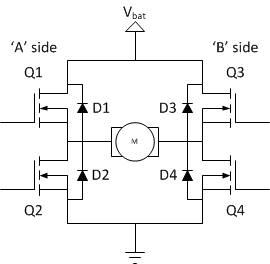
I have been working on a circuit go make a solenoid switch polarity with arduino. I originally used transistors (NPN) rated for 1A and 625mW in between the ends of the solenoid and ground. These all burned out when the polarity of the solenoid was switched (using a relay and switching which transistor was open and closed). I did the math and with a 60 ohm solenoid the voltage drop should be almost fully across the solenoid so the 10 V should be dropped across the solenoid, and the current should be (and was limited to using my DC power supply) .5A. I think this has something to do with inductance but I cannot figure out exactly what? I have solved this by using MOSFETs that can deal with higher power but I still need an explanation for why the transistors burned out. Thanks -Noam
Thank you so much for the explanation. My problem now is when I reverse the direction of the current that diode will simply short out the circuit. I could put a transistor after each diode but is there a better way of doing this?
The issue is if In order to switch the polarity of the solenoid I reverse the ground and power so if I put diodes there most of the current would simply flow through one of the diodes (I would need 1 in each direction the circuit always including when the ground and power are flipped from their original position using a relay and transistors) to ground shorting out my circuit

