2
\$\begingroup\$

I have an application where a push button and mechanical grey-code rotary encoder(user inputs) need to mounted away from main pcb. 24" - 48" away. This is for space and packaging reasons.

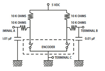
Is it OK to have the debouncing RC circuit on the PCB and the switches/encoder remotely connected via cable, or does the debouncing circuit need to be with the switches?

Encoder circuit from datasheet:

enter image description here

\$\endgroup\$

3 Answers 3

5
\$\begingroup\$

The debouncing (and any noise filtering, ESD protection circuits) should be on the main PCB.

The switches themselves don't need anything local to them, nor would be be optimal to have additional circuitry there.

Edit: If the Gray code encoder is active (optical or magnetic) some remote circuitry might be useful- certainly supply bypassing, maybe some series resistors on the outputs, perhaps even a local supply regulator.

\$\endgroup\$
5
  • \$\begingroup\$ The encoder is the mechanical type. \$\endgroup\$
    – GisMofx
    Commented Jul 29, 2015 at 13:45
  • \$\begingroup\$ Then, no worries. But do worry about ESD from fingers etc. Also RC is not a debouncing circuit unless it is combined with a Schmitt trigger input. RC may be used for other reasons (filtering and ESD) but debounce is easy and good in firmware. If it requires external debouncing you may be doing something wrong (like using port change interrupts rather than polling). \$\endgroup\$ Commented Jul 29, 2015 at 13:47
  • \$\begingroup\$ My device uses an event driven state machine and the button and rotary encoder are using interrupts. I'm using the "debounce" circuit suggested from the datasheet-I added it to my question. \$\endgroup\$
    – GisMofx
    Commented Jul 29, 2015 at 13:55
  • \$\begingroup\$ I suggest using polling at < 1kHz, not interrupts. Your events would be the de-bounced changes from the (timer interrupt-driven) polling routine. \$\endgroup\$ Commented Jul 29, 2015 at 14:00
  • \$\begingroup\$ I need to see how that will affect my code. Each states' main loop will need to have the polling routine added. Maybe I need to create separate a polling thread. Although, the current interrupt driven inputs do work with the system. \$\endgroup\$
    – GisMofx
    Commented Jul 29, 2015 at 14:05
0
\$\begingroup\$

Since you mentioned "application", I'm going to assume you are running code here which monitors the buttons and contacts. If that is the case I can tell you from my experience that it better to do your de-bouncing programmatically. Consider developing a function that you occasionally call to check for button hits. Without delving into any particular language, what the function would do is this...

  1. As a one time initialization, set a variable to the value of your systems millisecond timer, and maybe initialize a static 'button variable', as a bitmap of all your buttons, and set it to zero (or "-1" if "HIGH" is the default state of your buttons). Also, initialize two variables, one to represent your debounce time in milliseconds (start with 20, for example).
  2. When your application calls your function, it should check the button (or multiple buttons). If no button has changed state when compared to your stored variable, just return the existing stored button state variable.
  3. If any button has changed state, check your current system millisecond timer, subtract the time stored in the timer variable you previously initialized. If the difference is less than your debounce time, just ignore the change and return the unmodified button state variable.
  4. If you get to this step, then one or more buttons HAS changed state, AND at least your specified debounce time has passed. In this case, store the new button state in your button bitmap, re-initialize the timer to the current system millisecond time, and return the button variable.

Thats all there is too it. You've not only saved yourself at least 2 components per button (the RC network), and have effectively created a "brick wall" filter, much more precise and consistent than the RC network would be. In addition, you have made it very easy to change the all important debounce time without de-soldering parts.

One note on this methodology, it is also possible to call a similar function by interrupt instead of calling it as part of a round-robin sequence in your main program loop. In my opinion this is NOT a good idea, because a defective noisy contact would generate lots of interrupts which could easily bog down your program. Generally in larger systems where an interrupt actually does report button hits (like a keyboard interrupt in a computer), the button hits have already been pre-processed by a small dedicated MCU in the keyboard itself. If you're doing it in a smaller system, and doing ALL the de-bounce yourself, the method I'm suggesting is a better choice.

\$\endgroup\$
4
  • \$\begingroup\$ I like the software approach, but I am using interrupts for the button and encoder. The application is an "event driven state machine". \$\endgroup\$
    – GisMofx
    Commented Jul 29, 2015 at 13:53
  • \$\begingroup\$ You can still probably set a timer interrupt that fires as often as your chosen debounce time, which makes the function I suggesting even easier. :-) When a button change is found, it is then already confirmed as de-bounced, by virtue of the timer rate. Once detected, you can directly queue a pending state in your state machine. I guess I just don't like the psudo "integration" response of RC filters for de-bouncing, and I guess a bit of cheapskate when it comes to eliminating parts (probably because I end up stuffing so many boards in my own garage ;-) \$\endgroup\$
    – Randy
    Commented Jul 29, 2015 at 14:16
  • \$\begingroup\$ To me, it seems a little tricky with polling with the graycode encoder because I'm looking for two inputs and monitoring which one changed first. I'd almost prefer the hardware solution for the encoder. \$\endgroup\$
    – GisMofx
    Commented Jul 29, 2015 at 14:53
  • \$\begingroup\$ Here's my final 2¢. I actually used a grey code rotary encoder recently for an audio volume control. Of course the gray code itself guarantees only one contact could be changing at a given time which was nice, but the polling with software debounce worked out pretty well. For one thing, by varying the debounce I was able to control (or maybe limit) just how quickly the user was allowed to vary the volume with a quick twist of the knob. It took me a while to determine the ideal debounce setting, but it sure would have been a pain doing those experiments having to change an RC network. \$\endgroup\$
    – Randy
    Commented Jul 29, 2015 at 15:55
0
\$\begingroup\$

Whether it's better to handle button debounce programmatically, in hardware, or a combination of the two, depends upon the nature of the bounce. Some kinds of button have a resistance which can change erratically as they are pushed; if they are pushed slowly, this erratic period can be spread over a substantial fraction of a second. If a processor can distinguish between a low resistance, high resistance, and open-circuit, ignoring button presses until low resistance is detected, and ignoring releases until open-circuit is detected, will work well. If a processor cannot make such distinctions, however, there may be a limit to much software alone can do without some extra hardware.

The most robust approach in many cases is to design a system with both normally-open and normally-closed contacts; such an approach can yield near zero quiescent current in both the button-pushed and button-not-pushed states, while suffering from essentially zero bounce of any form. I see no technical impediment to designing a rotary encoder with similar functionality, but I don't know of any such encoders in existence.

\$\endgroup\$
2
  • \$\begingroup\$ Makes sense. Do you agree that if any hardware debouncing is implemented that it can be remotely placed away from the physical switch/button, encoder? \$\endgroup\$
    – GisMofx
    Commented Jul 29, 2015 at 15:00
  • \$\begingroup\$ @GisMofx: What is important is that the signals which are necessary to yield a robust output be available wherever the debouncing is handled. If one were to e.g. have a group of buttons feeding a 74HC165 shift register, and they had the "dubious resistance" problem I mentioned, hardware to help with the debouncing would need to happen before the shift registers (though such hardware could perhaps take the form of pull-ups that could selectively pull to 2.8 or 3.3 volts). \$\endgroup\$
    – supercat
    Commented Jul 29, 2015 at 15:07

Your Answer

By clicking “Post Your Answer”, you agree to our terms of service and acknowledge you have read our privacy policy.

Not the answer you're looking for? Browse other questions tagged or ask your own question.