4
\$\begingroup\$

I am sending a 10 MB/sec digital data stream by amplitude moduating a infrared quantum cascade laser. The laser requires a hefty bias of about half an amp (which drops about 8.5 volts across the laser). I am mixing the digital signal with the bias using a broadband bias-tee (a Picosecond Pulse Labs 5546). The bias-tee expects a 50 ohm load on the AC+DC port. When I use a 50 ohm power resistor to terminate the line, all is well and the signal looks good on the scope. However, when I use a load that simulates the laser (a 5 watt 8.2 volt zener in series with a 1 ohm resistor) there is extreme ringing. This could be expected, since the dynamic impedance of this simulated load is about 2.5 ohms (the dynamic impedance of the laser is about 4 ohms at 500 ma).

I cannot just increase the load impedance with a series resistor, because at half an amp it would generate about 12 watts of heat inside the temperature-controlled laser enclosure. However, the modulation amplitude is only about 70 ma, which at 50 ohms generates only a quarter watt, which is acceptable. So what I need to do is present a 50 ohm load to just the RF and not the DC.

Is there an off-the-shelf device that will do this? If not, are there design examples of a passive network for this purpose?

\$\endgroup\$

5 Answers 5

4
\$\begingroup\$

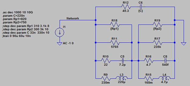
After much experimentation in LTSpice, I devised a passive network that should work. R9, R10, R11 and C5 are internal to L3. R15, R16, R17 and C8 are internal to L4.

enter image description here

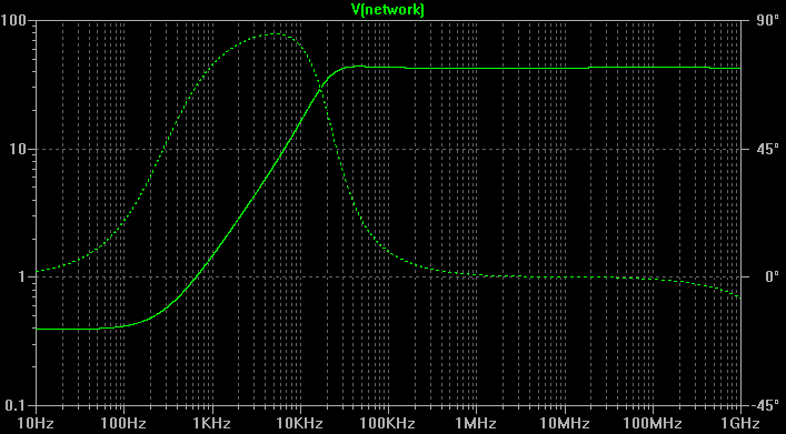
Here is the wideband AC analysis:

enter image description here

\$\endgroup\$
2
\$\begingroup\$

I'm just guessing here, but I'd guess it's some form of AC termination: basically a resistor and cap in series to GND. If your data stream is DC balanced then the cap is usually around 0.1 uF and the resistor is 50 ohms. If your data stream is not DC balanced then the cap is less than 800 pF, and the resistor is still around 50 ohms.

Note: This termination is ideal if your datastream is DC balanced. If it's not balanced, then you are really just trying different values until you find something that works-- it's not ideal, but it's close.

\$\endgroup\$
10
  • \$\begingroup\$ The data stream is balanced in that there are as many "1" bits as "0" bits. However, I still need to pass the DC with little or no additional series impedance, so just a cap and resistor is not enough. A cap a resistor in parallel to a series of inductors might work. \$\endgroup\$ Commented Aug 16, 2011 at 2:13
  • 1
    \$\begingroup\$ @ThomasMcLeod The cap will block the DC, so any current through the termination will be as a result of just the AC part of the signal. \$\endgroup\$
    – user3624
    Commented Aug 16, 2011 at 2:22
  • \$\begingroup\$ @Thomas, David is correct here. This is the form. The capacitor is closer to short as you go higher frequency, for your highest spectral content design the termination to be a match. It will mismatch as your frequency goes lower, but as you go lower it should matter less. This is the price you pay for no DC power. This does not affect series impedance. \$\endgroup\$
    – Kortuk
    Commented Aug 16, 2011 at 2:32
  • 1
    \$\begingroup\$ I don't see how this is possible. A series RC termination (50Ω+C) across a dynamic impedance of 4Ω will result in a net termination of 3.7Ω at HF. Isolating the laser with a series inductor could give the correct AC termination but will block the data from the laser & defeat the object. \$\endgroup\$
    – MikeJ-UK
    Commented Aug 16, 2011 at 7:50
  • \$\begingroup\$ @MikeJ-UK - He's probably operating the laser right at it's threshold voltage, or modulating the data onto a continuous laser output. The laser does not need to be hard-on or hard-off, the brightness just needs to vary enough to be detected at the other end. \$\endgroup\$ Commented Aug 16, 2011 at 9:48
2
\$\begingroup\$

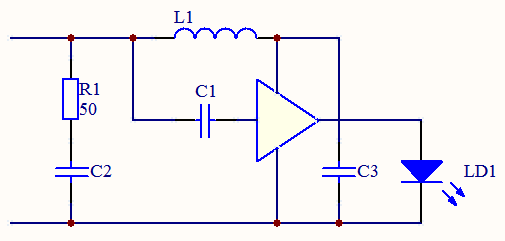
As I said in my comments, I don't see how this can be done. Having said that, I'm not sure why you want to add the signal and bias in this way. I only have a little history with communications lasers (and that was a long time ago) but I would expect a laser driver circuit which uses feedback from an integrated PIN diode to ensure that the minimum current (signal + bias) is just above the lasing threshold.

If you really need to add the signal to the bias remotely, the only way I can see is to separate the signal from the power and use a driver circuit to drive the laser.

enter image description here

\$\endgroup\$
2
  • \$\begingroup\$ This isn't a conventional com diode as one might use to drive fiber. We do not modulate through lasing threshold; the application requires only about a 20% modulation depth. It's an infrared spectroscopy application. The signal is actually a digital tag that identifies the laser. Others have tried adding the signal through current injection at the laser head, but that has it's own set of problems. So I'm trying the bias-tee. By the way, what is the part number of the amp in your drawing? \$\endgroup\$ Commented Aug 16, 2011 at 15:32
  • \$\begingroup\$ @ThomasMcLeod - Interesting application (and way outside my experience) The amp block just represents some hypothetical driver I'm afraid! \$\endgroup\$
    – MikeJ-UK
    Commented Aug 16, 2011 at 15:47
1
\$\begingroup\$

The real problem here is not that the bias T wants a 50 ohm load, but that the transmission line between that and the laser demands an impedance match.

There are several potential ways to solve this

  • connect the transmission line to the laser through the parallel combination of an inductor (to pass the bias) and a 47 ohm resistor (to raise the AC impedance to approximately that of the line)

  • if the above resistor would convert too much power (from the AC modulation alone) to heat within the enclosure, the resistor and inductor can be moved to the source end. Measurements anywhere midway on the transmission line will show distorting reflections, but they will be mostly absorbed in the source resistor before they can reflect again to the load end and distort the applied modulation

  • more efficient delivery of modulation power would use an impedance matching transformer to match the low laser impedance to the 50 ohm line impedance, the impedance ratio being the square of the turns ratio. An inductor bridging the transformer could couple the bias supply. However, a lossless (no resistor) matching network will not provide any place to safely absorb the consequences of any mismatch that does occur, and any reactance of the laser load will be presented back to the modulation source - so matching the modulation driver to the bias T/transmission line source end with a resistor would also be useful.

\$\endgroup\$
4
  • \$\begingroup\$ I'm not sure how you insert the transformer. Can you supply a drawing? \$\endgroup\$ Commented Aug 16, 2011 at 16:58
  • \$\begingroup\$ Sorry, I don't have suitable software handy, but I've entirely rewritten the answer to reorganize it. \$\endgroup\$ Commented Aug 16, 2011 at 16:59
  • \$\begingroup\$ These are good ideas. However, I can't use the transformed laser impedance itself for termination because it's a nonlinear device and the impedance varies with current (from about 3 ohms to 5 ohms). Second, the digital signal is wideband (from 1 kHz to 100 MHz) so that is a problem if the transformer is actually passing the signal. \$\endgroup\$ Commented Aug 16, 2011 at 17:48
  • \$\begingroup\$ Sounds like you want the resistive match then, if you have the power to waste. Or construct a transmission line with a different impedance (consider pipe/tubing). Note thought that transformer coupling is pretty common, specified in wired ethernet for example. \$\endgroup\$ Commented Aug 16, 2011 at 17:55
0
\$\begingroup\$

you can just use an impedance matched modulation source. it will swamp the reflected power and should eliminate the ringing. note that the signal will not look fine at the source, even when it is fine at the laser diode.

\$\endgroup\$

Your Answer

By clicking “Post Your Answer”, you agree to our terms of service and acknowledge you have read our privacy policy.

Not the answer you're looking for? Browse other questions tagged or ask your own question.