101
\$\begingroup\$

The datasheet of the 24LC256 EEPROM states that:

The SDA bus requires a pull-up resistor to VCC (typical 10 kΩ for 100 kHz, 2 kΩ for 400 kHz and 1 MHz).

I thought that any resistor with a kΩ value would do the job (and it seems that my EEPROM works fine at different frequencies with a 10 kΩ resistor).

My questions are:

  • is there a correct value for pull-up resistors ?
  • is there a law/rule to determine this value ?
  • how do different resistance values affect the I²C data bus ?
\$\endgroup\$
1

11 Answers 11

89
\$\begingroup\$

The correct pullup resistance for the I2C bus depends on the total capacitance on the bus and the frequency you want to operate the bus at.

The formula from the ATmega168 datasheet (which I believe comes from the official I2C spec) is --

$$\text{Freq}<100\text{kHz} \implies R_{\text{min}}=\frac{V_{cc}-0.4\text{V}}{3\text{mA}}, R_{\text{max}}=\frac{1000\text{ns}}{C_{\text{bus}}}$$

$$\text{Freq}>100\text{kHz} \implies R_{\text{min}}=\frac{V_{cc}-0.4\text{V}}{3\text{mA}}, R_{\text{max}}=\frac{300\text{ns}}{C_{\text{bus}}}$$

The Microchip 24LC256 specifies a maximum pin capacitance of 10pF (which is fairly typical). Count up the number of devices you have in parallel on the bus and use the formula above to calculate a range of values that will work.

If you are powering off of batteries I would use values that are at the high end of the range. If there are no power limits on the power source or power dissipation issues in the ICs I would use values on the lower end of the range.

I sell some kits with an I2C RTC (DS1337). I include 4K7 resistors in the kit which seems like a reasonable compromise for most users.

\$\endgroup\$
2
  • 3
    \$\begingroup\$ Typically I would imagine the bus to be idle (de-asserted) the vast majority of the time, so for a battery application there are more important issues to deal with than trying to optimize I2C pullups just so :P \$\endgroup\$
    – Nick T
    Commented Oct 2, 2010 at 3:02
  • 8
    \$\begingroup\$ only thing i would add is a buffer above the summed capacitance of the devices on the bus. The trace itself as well as the solder joints from pads to pins will also have some impedance. On longer buses the capacitance of the trace/wire can be larger than the pin capacitance of the devices. When designing production boards i don't usually determine the final pull up value till i have a prototype in hand and can scope the bus with various values. \$\endgroup\$
    – Mark
    Commented Oct 4, 2010 at 2:01
28
\$\begingroup\$

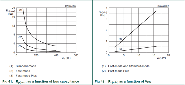
It makes sense that higher frequencies require lower resistance pull-ups: a lower resistance will charge/discharge the cable's capacitance faster, which results in steeper edges. With the wider pulses of lower frequencies a less steep edge won't influence the pulse's shape as much.

Therefore the I2C specification gives maximum values for the pull-up resistors as a function of bus capacitance for three speed classes:

enter image description here

The minimum values are defined in function of the bus voltage, and should limit the current through the drivers.

\$\endgroup\$
2
21
\$\begingroup\$

There is a correct range of values, however it is difficult to describe exactly what that range is. Generally, 10k works.

Digital outputs have a specified ability to source or sink current. If your output could sink 5 mA and the output was connected through a pull-up to 5 V and then set to 0, you would need a minimum of 1k resistance. If you use less than 1k, the output will not be able to sink enough current to pull the pin all the way down to 0V. If you use a bigger value, like 10k, then the pin only has to sink 0.5 mA, which is much less than it's rating.

Digital inputs have a specified leakage current. This is kinda like the amount of current it takes to "maintain" a 0 or 1 at an input. If your pull-up resistor is too large, then it won't be able to overcome the leakage current. If it just barely overcomes the leakage current, then any noise in the circuit could be enough to change the input.

When using digital outputs that can sink and source current ("totem pole driver", "push-pull driver"), you might be tempted to not use pull-up or pull-down resistors. However, it is very important that CMOS inputs not be allowed to float or they can pull excessive current...and it's very easy to forget that bidirectional MCU pins usually come up as inputs!


I2C and other protocols like it use "open drain" (or "open collector") outputs. Instead of having outputs that can pull up and down, and open drain outputs can only pull down. That is why the external pull-up resistor is required. There are now additional restrictions on the range of pull-up resistors; the pull-up value will form an RC circuit with the bus capacitance. Too small of a value will once again prevent the output drivers from sinking enough current to pull the pin all the way down to 0. However, too large a value will take too long to charge the bus capacitance up.

If there are setup/hold times that you are not allowed to violate, those will help you determine an RC time constant. The bus capacitance is largely determined by PCB layout, so you can then pick an R value that combines with the C to provide a value that is comfortably within the setup/hold time for your digital input.

\$\endgroup\$
15
\$\begingroup\$

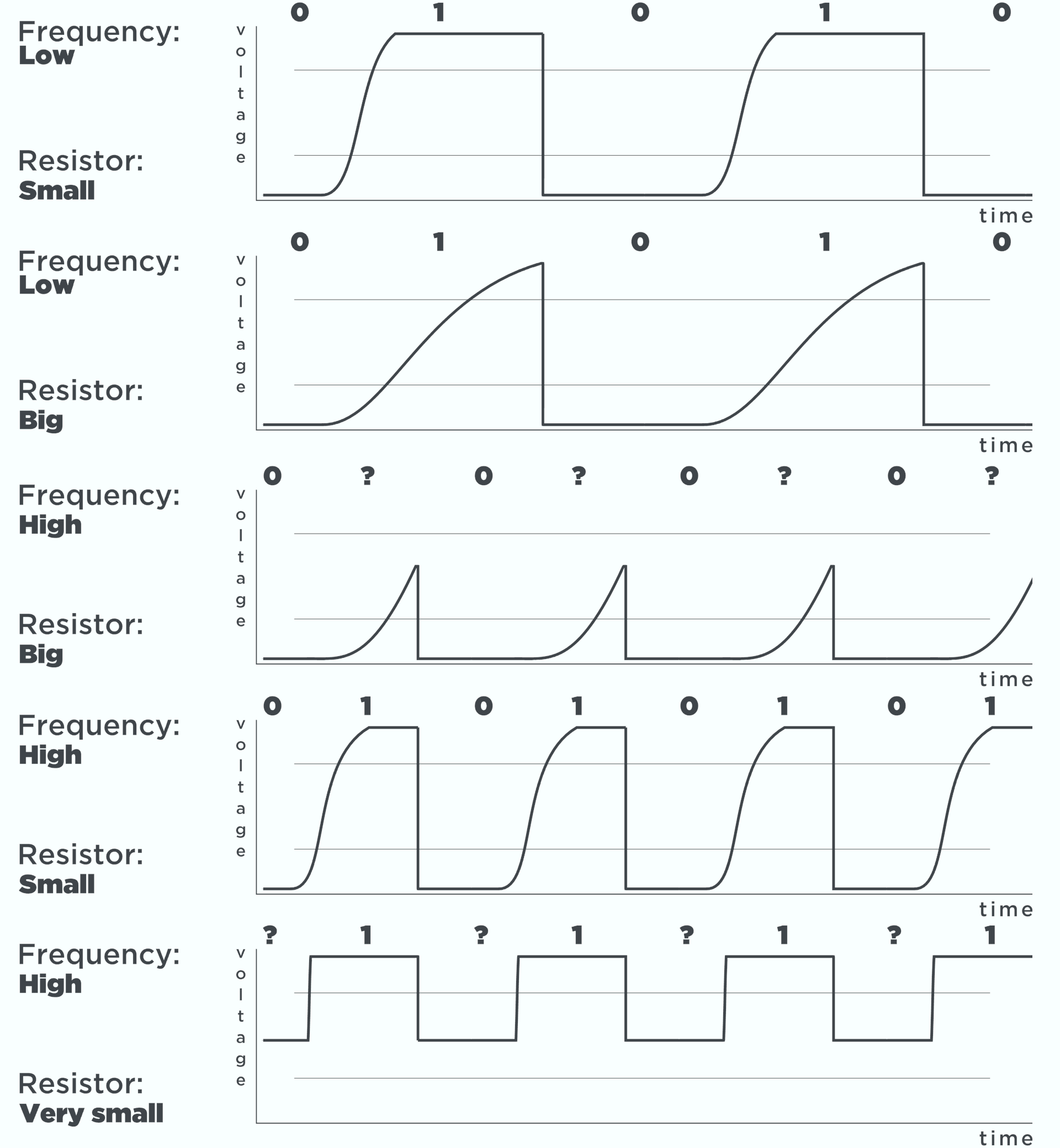
if you ask me the best thing is to look at each project with oscilloscope if you think it is critical. You can do the math, but... it is better to measure it :) because impedance (length of lines and so on) have a big factor.

There is a gif animation of effect of different values on my website:

DEFUNCT: https://small-roar.com/i2c-inter-integrated-circuit/

As you can see too small value results in not detecting of signal - with older MCUS like Atmega it is not a problem because they have high values for "logic low/high" + if you want low power application its not the best way to go.

enter image description here

\$\endgroup\$
14
\$\begingroup\$

Low pull-up values (lower resistance) can improve the edges of the signal transitions but can sometimes be too stiff - if the devices on the bus cannot sink the pull-up current you get logic 'low' which isn't really that low, which can cause communication errors (and much pain.)

I would go with the highest pull-up resistance that gives you reliable communications.

\$\endgroup\$
10
\$\begingroup\$

An issue I haven't seen mentioned yet is power consumption. If one is using a 3.3 volt supply, a 3.3K resistor to ground will waste 1mA of current (3.3mW of power) whenever an output is low. Using a 10K resistor would reduce both current and power by a factor of three. If there will be a lot of communication on the I2C bus, that power consumption may end up being a significant portion of overall power drain especially if the bus may sit low for extended periods of time. For example, if one is reading 100 bytes/second but after reading each byte the bus is left with the device outputting the first bit of the next byte, and most of those bytes are have the MSB clear, the bus may spend 90% of the time with SCL and SDA low. Depending upon what else the system is doing, that could massively increase power draw.

To save power, it may be helpful to have a "pull-up" resistor connected to an I/O pin rather than to VDD. While I haven't seen hardware I2C implementations offer support for this, having the master output data on a separate I/O pin that's connected to the bus via resistor rather than using an open-collector driver and a fixed pull-up resistor will avoid wasting current when the master wants to output a "0". In addition, if the master is going to leave SCK low for awhile without caring about what's on SDA, the master may disable the pull-up until it's ready for some more communication. If none of the devices need to use clock stretching, the master can simply use a direct output for SCK and not bother with any pull-up on that wire.

If one is using software bit-banging with a fast processor, and one wants to get good performance despite high bus capacitance, the above approach can be combined with the use of a processor's built-in weak pull-ups. When reading data, turn on a very strong pull-up, briefly, immediately after each falling edge of SCK, and then switch to a weak pull-up. The strong pull-up will pull the line high despite the capacitance, and once the line is pulled high the weak pull-up will be able to keep it high. Even if a device would have trouble pulling the line low against the strong pull-up, it would be able to do so once the strong pull-up is switched off.

\$\endgroup\$
1
  • 1
    \$\begingroup\$ Thank you for this answer! When doing battery powered or low heat devices, every little bit helps. \$\endgroup\$
    – Bryce
    Commented Apr 13, 2020 at 16:48
7
\$\begingroup\$

For low frequencies the value doesn't really matter, but for high frequencies it can have a filtering effect on the signal, in combination with other capacitances in the circuit, which is why they recommend different values for different speeds.

\$\endgroup\$
1
  • 3
    \$\begingroup\$ I know this is a very old answer but I want to comment that the resistor value does matter at low frequencies. If the resistor value is too low then the open-collector outputs will not be able to pull the signal lines down to a valid logic 0 level. \$\endgroup\$ Commented Mar 12, 2021 at 13:31
6
\$\begingroup\$

Minimal resistor value depends on driving capabilities of two sides of the bus. For example they drive 10 mA, so your resistor value should be greater than \$\frac{V_{bus}}{10~mA}\$. It is not exact resistor value, it depends on your bus capacitance. You can check your resistor value whether it is correct or not, by measuring rising time and falling time of bus pulses. You can find these time values in below link:

http://www.cypress.com/knowledge-base-article/rise-and-fall-time-specifications-scl-and-sda-lines-i2c

\$\endgroup\$
1
  • \$\begingroup\$ Your answer is relevant. Indeed it is not an exact value but, IMO, it is a safe approximation. However, note that the minimum resistor value should not take the bus capacitance into account and it should only depend on the maximum current you want to allow on the bus. \$\endgroup\$
    – Krauss
    Commented Dec 7, 2020 at 9:20
3
\$\begingroup\$

Assuming you want to maximize the speed while keeping the current consumption at minimum. It's pretty easy to calculate the maximum and the minimum resistor values. This is explained in this datasheet.

Bus capacitance

First, we need to know the bus capacitance. It is true that you can make a rough estimate it by adding the pin capacitance of the drivers. However, if you are developing a product, you can assemble a prototype with whatever test resistance and calculate a more accurate value.

In the referred datasheet, the following equation is derived:

$$t_r = t_{0.7V_{CC}} - t_{0.3V_{CC}} = 0.8473 \times R_{P} \times C_b$$

You can measure the rise time on your test set up and plug the highest in to the equation:

$$C_b = \frac {t_{r{Max}}}{ 0.8473 \times R_{P_{test}}}$$

With this value, you can also validate if your system meets the maximum bus capacitance allowed by the specification.

Maximum resistance

After you get the capacitance, you can plug the capacitance back in the equation to get the maximum resistor values for your system:

For standard mode: $$R_p(max) = \frac {1000ns}{ 0.8473 \times C_b}$$

For fast mode: $$R_p(max) = \frac {300ns}{ 0.8473 \times C_b}$$

For fast mode plus: $$R_p(max) = \frac {120ns}{ 0.8473 \times C_b}$$

Minimum resistance

This is the easiest calculation, just divide the maximum bus voltage drop by your maximum target current:

$$R_P(min) = \frac{V_{CC}-V_{OL}(min)}{I_{OL}}$$

Note: In the datasheet they specify VOL(max). I believe it is a typo. In any case, this answer provides a safe quick calculation.

\$\endgroup\$
1
\$\begingroup\$

Regarding the first two questions I believe they were aduately answered. Regarding the third: As others mentioned, pull-up values along with cable capacitance play a big role both in whether your devices are recognized and the speed you are able to achieve as they effectively form a low-pass filter.

For a recent project I had to drop the pull-up resistors value very low (510Ohms) to run a 50m I2C bus over plain old flat telephone cable at 5v. This is well out of I2C specs (min ~1,5KOhms pull-ups for 5V at 3mA) but it works.

\$\endgroup\$
2
  • 1
    \$\begingroup\$ Hello and welcome to the site! Stack Exchange sites are something very purposefully distinct from traditional internet forums. Here we do only specific questions and specific answers. The answer form is reserved only for posting actual answers, ie, solutions. It must never be used to make general commentary, share personal experiences that are not actually an answer, give thanks, or ask questions. \$\endgroup\$ Commented Oct 9, 2020 at 16:00
  • \$\begingroup\$ Welcome to EE.SE but I'm not sure that this answers the questions: (1) is there a correct value for pull-up resistors? (2) is there a law/rule to determine this value? (3) how do different resistance values affect the I²C data bus? Stack Exchange sites are Q&A sites rather than a forum. See the Tour for details. \$\endgroup\$
    – Transistor
    Commented Oct 9, 2020 at 16:01
1
\$\begingroup\$

According to the I2C bus specification The I2C pull up resistor value mainly depends on the I2C mode (Standard / Fast / Fast Plus / HS), VDD and the bus capacitive load.

It's minimum value is calculated using the following equation:

Rpmin = (VDD – VOLmax) / IOL

Where:

  • VDD: Power supply voltage
  • VOLmax: Maximum LOW-level output voltage
  • IOL: LOW-level output current

While, it's maximum value is calculated using the following equation:

Rpmax = tr / 0.8473 x Cb

Where:

  • tr: Maximum rise time of signal ( SDA / SCL / SDAH / SCLH)
  • Cb: Maximum capacitive load for bus line

I have built an online tool for sizing the pull up resistor at different bus modes. You can access it here.

\$\endgroup\$
3
  • 3
    \$\begingroup\$ This isn't spam, they disclosed affiliation, which is fine by SE's policy \$\endgroup\$
    – Voltage Spike
    Commented Mar 11, 2021 at 20:09
  • 1
    \$\begingroup\$ Let's clarify that the link at the end of this post directs you to a for-profit company's web site that also provides information about products that are for sale. \$\endgroup\$ Commented Mar 12, 2021 at 13:34
  • 1
    \$\begingroup\$ That should also be done with the link on the top. It redirects to an NPX resource, that is also a for profit company, much larger that the one that the link at the bottom redirects to. Although, if I might be permitted to point that out, it might have a bit more impact for the community to decide if that link provides the community with a helpful and time saving resource or not. Personally, I believe that my tool would have saved me a few hours or researching the i2c protocol. That is the reason I've invested my time in building it. \$\endgroup\$ Commented Mar 12, 2021 at 14:23

Your Answer

By clicking “Post Your Answer”, you agree to our terms of service and acknowledge you have read our privacy policy.

Not the answer you're looking for? Browse other questions tagged or ask your own question.