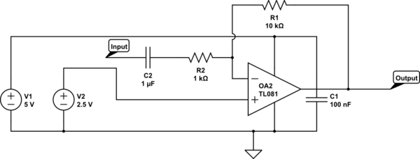
Coupling and decoupling capacitors are just normal capacitors like any other - it is their application that is being described, not their type. A quick example:

simulate this circuit – Schematic created using CircuitLab
This circuit is a simple amplifier, taking the signal at the Input node and removing any DC component, multiplying its voltage by -10 (i.e. inverting it with a gain of 10) and adding a 2.5 V DC bias to the Output.
Here, C1 is a decoupling capacitor. It decouples the AC from the power rail of the opamp - that is to say it reduces any ripple that might be present on the power rail to stop it affecting the opamp's performance. Additionally it reduces any ripple caused by AC current draw in the opamp affecting the stability of the voltage rail. You can think of it doing this in two equally valid ways.
You could say that C1 stores a small amount of energy that can be locally drawn from it to satisfy short-term current demands from the opamp without affecting the power rail voltage by drawing from V1, which may have a higher source impedance.
Alternatively you could consider C1 to be a relative short circuit to AC voltages, but a relative open circuit to DC. Hence C1 is "shorting out" the AC on the power rail to ground.
Decoupling capacitors tend to be physically located close to the IC they are intended to decouple to avoid the effective of parasitic inductance and resistance of long traces affecting their ability to supply current peaks.
C2 is an AC coupling capacitor. It only allows the AC component of any signal at the input to pass through to R2 and hence the amplifier. It blocks any DC, allowing us to avoid amplifying any DC element from a previous stage. This is often useful in instrumentation amplification, audio amplifiers and signal conditioning.

