1
\$\begingroup\$

This is my first question of Electrical Engineering SE.

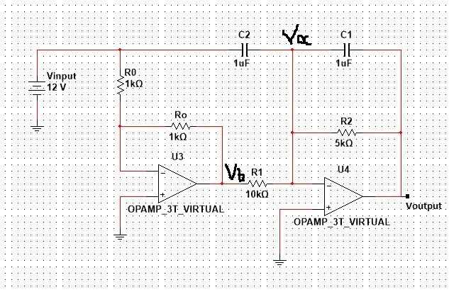
I have the following circuit. enter image description here

I want to calculate it's transfer function, considering ideal Op amps and circuit elements. I have almost completed the analysis of the circuit. Vb = -Vinput because of R0 = Ro and i know that the second Op Amp U4 acts as a mixer, it will add two signals accordingly (based on superposition theorem). I want to ask one thing that is not clear to me. What is the voltage entering the inverting input of the second Op Amp? Not in numbers, in terms relative to the other voltages we know that are present in the circuit such as Vinput. What is not clear to me is that the capacitor (non polarized) C2 lies between Vin and Va(ground) and therefore it creates a voltage drop (or does it?). Also Va should be zero because of virtual ground of Op Amp U4. Therefore does that mean that the second signal on the inverting input of U4 is Vinput? (never mind the first signal, that one is coming from the first op amp and it's -Vinput*(other stuff)) I'm confused with this. If someone could help me out i would be very grateful. Don't consider values of capacitors or R2, R1. I want to understand the logic behind this particular thing. Thanks in advance!

\$\endgroup\$
1
  • \$\begingroup\$ Do you assume that C2 could transfer a DC voltage Vin to the U4 opamp input? \$\endgroup\$
    – LvW
    Commented Aug 23, 2015 at 17:02

1 Answer 1

2
\$\begingroup\$

Start by analyzing the steady state. That means all capacitors are open circuits. The first opamp then just inverts Vinput with respect to ground. The second then inverts it again, but with a gain of 1/2. Therefore Voutput = Vinput / 2.

Since both opamps are ideal and have feedback so that they operate in their linear region, the negative inputs of both will be held at 0 V.

Analyzing the dynamic behavior is more tricky, but you already know what the steady state will be after everything settles. C2 feeds current proportional to the derivative of Vinput into the node at the negative input of the second amp. This will add to the steady state signal. Voutput will therefore have a component that is proportional to -dVinput/dt.

C1 and R2 form a high pass filter, which in the feedback path results in a the second stage being a low pass filter. Whatever the Voutput would have otherwise been, it will be low pass filtered by a single pole at 1/2πR2C1. When R is in Ohms and C in Farads, then this expression is in Hz.

\$\endgroup\$
0

Your Answer

By clicking “Post Your Answer”, you agree to our terms of service and acknowledge you have read our privacy policy.

Not the answer you're looking for? Browse other questions tagged or ask your own question.