How does a sine choke exactly function? In most high power inverter systems, the primary side of the output transformer is always driven by a PWM signal. The secondary output which is sent to a load should also come out to be PWM. How does a pure sine wave inverter exactly convert this PWM into a pure sine wave?
-
\$\begingroup\$ It uses several steps wave output. See picture here invertershop.com.au/… \$\endgroup\$– OkaCommented Sep 23, 2015 at 10:44
-
\$\begingroup\$ Vishal are we done here? Can we close this Q and A session with you accepting an answer or, do you need more clarification about something? \$\endgroup\$– Andy akaCommented Oct 3, 2021 at 14:52
-
\$\begingroup\$ Hello, Andy. Yes I am done. This can be closed. Thank You, \$\endgroup\$– VishalCommented Mar 31, 2022 at 7:24
-
\$\begingroup\$ @vishal please accept an answer as per these stack exchange guidelines --> What should I do when someone answers my question. \$\endgroup\$– Andy akaCommented Mar 22, 2023 at 12:21
4 Answers
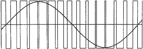
Here's a PWM signal fed to a transformer and superimposed on this diagram is the sinewave that the PWM represents: -
The secondary of the transformer usually has an inductor and a capacitor that form a 2nd order low pass filter thus converting the PWM signal into (more-or-less) a fairly decent sinewave.
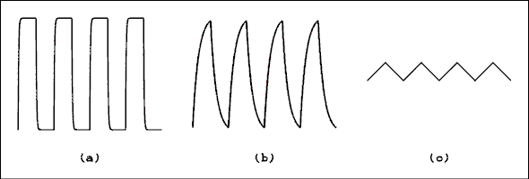
For instance, if you take the high frequency content of the PWM waveform it looks like a square wave with varying duty cycle and, you can low-pass filter this quite easily to get this: -
On the left is the original square wave. In the middle a little bit of filtering has happened and on the right the filtering is far greater.
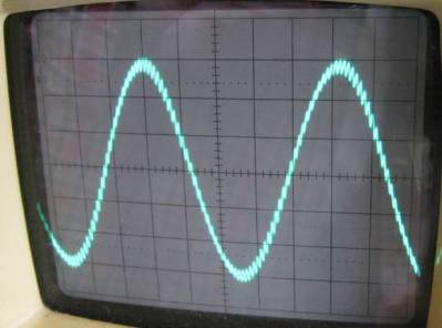
Thus, the high frequency edges of the PWM signal can be greatly reduced leaving the low frequency content that represents the sinewave. In effect you get something that typically looks like this: -
You can still see that the waveform has a little bit of the PWM signal but, in the main, it is a sinewave.
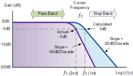
If your PWM frequency is 60 kHz and your AC is 60 Hz you could position a filter to have a cut-off of 600 Hz and there would be 2 decades between it and the 60 kHz. A 2nd order filter would attenuate the 60 kHz by 80 dB (40 dB per decade): -
You might note that I mentioned a filter having a cut-off of 600 Hz and wonder why it is position ten times higher than the AC 60Hz. You might ask why not have it at 60 Hz and this would be a good question. The reason it isn't at 60Hz is two-fold: -
- There would be a 3dB attenuation of the AC
- If the filter was extremely resonant it would consume vast amounts of current because, in effect, it is also a series resonant circuit across the line.
It has to be positioned as far away from 60 Hz as possible to avoid large circulating currents in the L and the C of the filter BUT you don't want it up close at 60 kHz because it won't filter out the high frequency content very well. Minimum is 100 Hz I would say and it should be at least 1 decade away from the lowest PWM frequency (generalism alert!).
-
\$\begingroup\$ Is it better to pwm in an H bridge such that the filter sees pulses from peak to 0v and the pulses fom 0v to negative peak, like forum.allaboutcircuits.com/… rather than alternating pulses between peak and negative peak as depicted in your picture? \$\endgroup\$ Commented Mar 23, 2017 at 0:45
-
\$\begingroup\$ If you should use a H bridge then yes, it is probably more energy efficient to be a little clever in the way PWM is produced. If you are not using a H bridge there is no option of course. \$\endgroup\$– Andy akaCommented Mar 23, 2017 at 8:05
The basic answer is by low pass filtering. The slower "average" of the PWM waveform is the desired line frequency (like 60 Hz) signal. Superimposed on this signal is the high frequency PWM chopping.
The inductance of the transformer together with some capacitance on the output form a L-C low pass filter. This filter passes the 60 Hz component with little attenuation, but greatly attenuates the many kHz PWM chopping frequency.
Switching power supplies in general work on this concept. The pulse signal contains a deliberate low frequency component, which is ideally all that makes it to the output.
You have two options:
1. Low voltage DC is step-uo converted with push-pull PWM and step-up ferrite transformer at high frequency, it can be also a flyback converter or phase shifted PWM converter rather than push-pull. At the secondary of HF transformer is a rectifier with caps and you get the HV DC voltage. The second stage is H-bridge with sine wave PWM that has to have an output lowpass LC filter to filter out high frequency.
2. DC voltage is inverted with sine wave PWM, then filtered with lowpass LC filter, then a classical step up transformer.
Just a small addition to the answer by Andy. If you carefully craft the PWM waveform it's possible to move the energy in the harmonics to higher frequencies to make them easier to filter out. Have a look for Harmonic Elimination Pulse Width Modulation. I've done a small write up about it. http://www.grant-trebbin.com/2013/10/harmonic-elimination-pwm-comparison-and.html
-
\$\begingroup\$ Thanks Grant for this innovative piece of information. I have never progammed in Octave, can you provide the same source in say Python? \$\endgroup\$– VishalCommented Sep 28, 2015 at 13:03
-
\$\begingroup\$ @Vishal I'll have a go at it. Not sure if the libraries I'll need are available. Might take a few days too. \$\endgroup\$ Commented Sep 29, 2015 at 19:41
-
\$\begingroup\$ @Vishal I managed to get a version of my code working in Python. It's more compact and easier to understand. <github.com/GrantTrebbin/HEPWM> \$\endgroup\$ Commented Oct 3, 2015 at 9:34
-
\$\begingroup\$ Thanks Grant for all the efforts. I am also happy to hear that as expected the Python code is shorter and easier to understand. \$\endgroup\$– VishalCommented Oct 4, 2015 at 12:50


