1
\$\begingroup\$

Essentially, I want to connect a really cheap musical toy with no outputs (other than a speaker) to line or instrument level equipment (for the full details, please refer to my previous question). The amplifier chip is a TDA2822L from Unisonic Technologies, driving a single 2.5W 8 Ohm speaker in the following arrangement (only connections for pins 1, 3 and 4 shown):
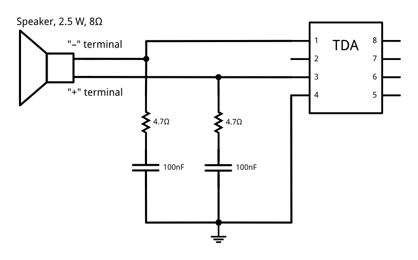
schematic of the TDA2822L circuit

(this follows the "bridge" configuration described in the datasheet, with the exception of reversing the order of the resistor and capacitor)

The IC runs on a 7.5 VDC supply current, provided by five AA batteries. Using fresh batteries (providing around 8 volts unloaded), setting the volume at maximum, I measured around 1 VAC RMS across the speaker terminals. I expect this to be a somewhat inaccurate reading, as the device is not capable of producing sustained tones, so I had to use a backing rhythm for measurement. Furthermore, I found that the multimeter I used (an older version of the VC820-1) has a fairly slow sampling rate, so it might have missed some peaks. With a reasonably safety margin, I think it's safe to say that the output remains below 1.5 VAC RMS.

I want to tap this signal and send it to a line level output, as well as an instrument level output (only one at a time, selected by a switch). I have a fairly solid idea of how this circuit should be assembled, but I am uncertain on a few points.

  1. Based on transistor's answer to my previous question, I figure for the line level output, I could just have a 10 Ohm pot between the output pins, like so (resistor+cap omitted for clarity):

    simplified schematic of the line level output

    I calculate that having 10 Ohms across the terminals as opposed to 8 would result in a roughly -2 dB signal reduction (compared to the original configuration) with the pot cranked up to the maximum. Is this calculation correct?

  2. If the above calculation is correct, is a -2 dB reduction (from 1.0–1.5 VAC RMS) enough to avoid damaging line level inputs? If not, what potentiometer should I use?

  3. For the instrument level output, I'm planning to add a series resistor before the pot:
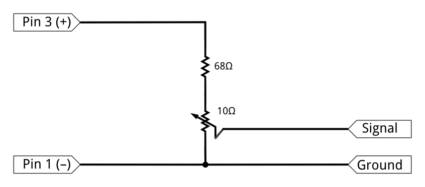
    simplified schematic of the instrument level output

    For these resistor values, I come up with a -17.8 dB signal reduction. Is this calculation correct?

  4. (assuming that the solution in 1. is acceptable for line level) What signal reduction from line level is necessary to avoid damaging instrument level equipment?

If the above simplified schematics above are acceptable, I will submit a final circuit design for feedback.

\$\endgroup\$

2 Answers 2

1
\$\begingroup\$

Fluff has covered it pretty well. I would make the following suggestions:

  1. Leave the speaker connected in the instrument. It will be useful for checking the "instrument" but, more importantly, may help retain some of the distortion due to the non-linearity of the speaker.

  2. The speaker has neither terminal connected to ground but you can take your tap-off between one output and ground - i.e., either pin 1 or 3 to 4.

  3. Since the output pins 1 and 3 will have half-supply voltage on them in the quiescent state you will need the DC blocking capacitor as you've stated. Make it big enough to avoid too much bass roll-off with the pot resistance. Use http://sim.okawa-denshi.jp/en/CRtool.php to assist.

  4. Remember for best signal to noise ratio (or, in this case, desired noise to unwanted noise ratio) you will want the volume up high on the instrument and your output divider will then be used to attenuate the signal and the noise.

\$\endgroup\$
0
\$\begingroup\$

TLDR version: Start with a 10K pot set to 1K from ground.

I just saw the bridge part (which wasn't in the old question). That means the output is taken out of phase from the two amps inside the TDA, so the max level it could reach is 2x the supply rail, i.e. 15V DC (ignoring that it can't swing all the way to rails).

If you're going to use an attenuator (pot on the output) anyway [your schematic is conceptually correct by the way], start with a larger-value pot, say 10Kohm [and you can forego the series resistor in that case at least for initial testing]. You'll get less current that way so won't need a [physically] beefy pot or worry about its wiper burning out. Pots have a power rating, check datasheet etc. The dinky ones can't handle more than 100mW dissipation typically. With a 10KOhm pot at 15V the most you cold see dissipated is 22.5mW [worst case being DC].

Initially I'd set the pot to 1Kohm (from ground), so taking just 10% of the voltage to the next stage. Your next stage is probably going be a mixer console which has its own [line-level] amplifier[s] anyhow. Remember that our perception of loudness is based on a an exponential scale (relative to the voltage/level), so even if you reduce the toy's signal to 1% of its original level, you'll still be able to hear it. And the mixer can [and does] reamplify this. Crank up the toy/instrument level later if necessary; higher level from the toy's amp usually means less noise (relative to signal) going on the wire to the mixer.

It's possible that this toy might rely on its own amplifier distorting significantly for its "signature" sound. In that case you may find out that with the [much] lower 10KOhm load it may sound rather different (never mind different speakers). If that turns out to be the case, you could switch to a lower ohmic-value pot (but capable of sinking more power). But let's not get ahead of ourselves too much.

As for what's a safe level for the mixer or whatever you plug this into... if you stay below 1V or so peaks you can probably use any consumer equipment. Otherwise, like I said in my previous answer, you need to check the specs/manual of whatever you're going to use on the receiving side. A 10K pot set to 1K (from ground) seems a safe bet in that regard as worst case [theoretical] peaks wold be 1.5V [and counting in that's not a rail-to-rail amp etc. you'll probably won't see that.] With this pot setting you could test with a consumer level line-in, e.g. PC soundcard, but beware of accidentally cranking up the pot too much. Also beware that the "mic in" jack on PCs is 100x voltage-amplified though (as is the headset on smartphones)... and it also applies significant DC bias on this line (for an powering an electret concondensr mic). For more production-like dummy-proofing, adding a series resistor as you thought is not a bad idea. But you'll need to determine experimentally what value is needed for limiting the toy's max volume to a usable level but safe depending on the intended receiving equipment and what you can (or cannot) hear.

\$\endgroup\$
1
  • \$\begingroup\$ That was really thorough, thanks! I'll try out some values later this week.I definitely want to add a series resistor, just in case someone tries to crank it up to 11. For the instrument level output, should I use the same total resistance with a lower ohmic value pot, would it be better to use a larger series resistor? E.g. if using 8k+2k (series resistor+pot) for line level, should instrument level be 9.5k + 500 or something like 20k + 2k? \$\endgroup\$
    – user88045
    Commented Oct 6, 2015 at 11:13

Your Answer

By clicking “Post Your Answer”, you agree to our terms of service and acknowledge you have read our privacy policy.