I am somewhat stuck and desperately need help. I am faced with the Traffic Light Problem, and I completely understand the actual logic of it. However, I am having great difficulty turning this into digital logic. I have thought through the state diagram. My biggest problem that I can't wrap my head around is that the State is represented by a two-bit binary number. So when building my circuit, how do I "create" this two-bit number using gates and what not?
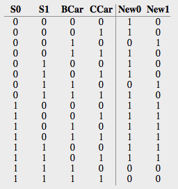
This is my simplified truth table for the problem. 4 states: new red light(00), existing red light(01), new green light(10), and existing green light(11) [the yellow light is being ignored in my version of the problem].
Reduced Truth Table
State Input  new State
  00    00     10
  00    *1     10
  00    10     01

  01    00     10
  01    *1     10
  01    10     01

  10    **     11

  11    0*     11
  11    1*     00
Now, I get how to brute-force design the output of each state+input to get each newState. I just am having a very difficult time bringing it all together. I have my State Diagram all drawn out and I get when the transition needs to happen, its the digital logic that I'm having trouble with
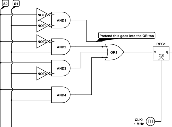
I still have much trouble with Multiplexers, although I know they would be usable in this schematic I have drawn below (because I have created a brute-force design from the State rather than the inputs)

simulate this circuit – Schematic created using CircuitLab
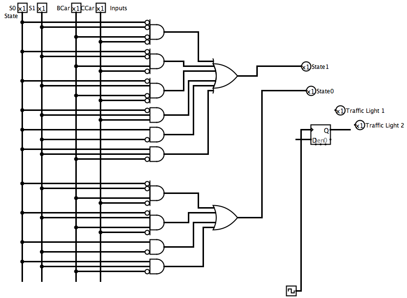
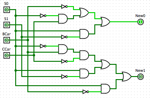
I have another much more complicated schematic that includes both the State and the Inputs, but I'm not sure if it is right or how to use it further (i.e. connect to flip flop and create an output of the traffic light color) [NOTE: THE OUTPUT IS WRONG, the output of the first OR gate should be S0 and the output of the second OR gate should be S1]
[ ]1
]1


