2
\$\begingroup\$

Iam trying to test my mosfet because my project which involved connecting a load to the drain did not work. After some tinkering Iam down to suspecting the mosfet (n-channel, IRF630B). I have connected it this way to test,

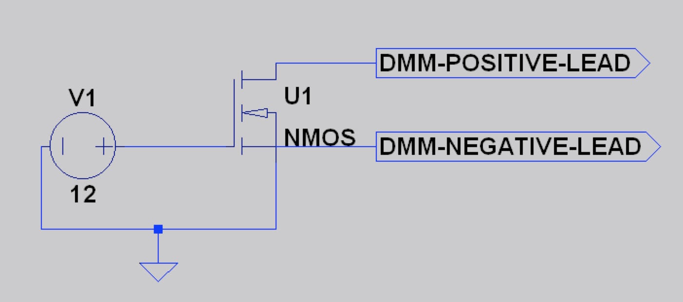
+12v -> gate, ground -> source

Then I switched my multimeter to measure resistance (200 ohm option) and connected the red lead to the drain and black lead to source.

Q1. Am I measuring the Rdson correctly? (it does not need to be accurate, good approx is enough)

Now, with power switched off, I see that the circuit is open. After switching on, the Rdson value is in the range of 10-11 ohms. I have tried 10 different mosfets and all show the same range. According to specs, anything above 10V should bias this mosfet correctly and bring down the Rdson drastically (ideal value is 0.4ohms). I also changed the power source to +19.5v to see if a harder drive makes a difference. I still got similar results.

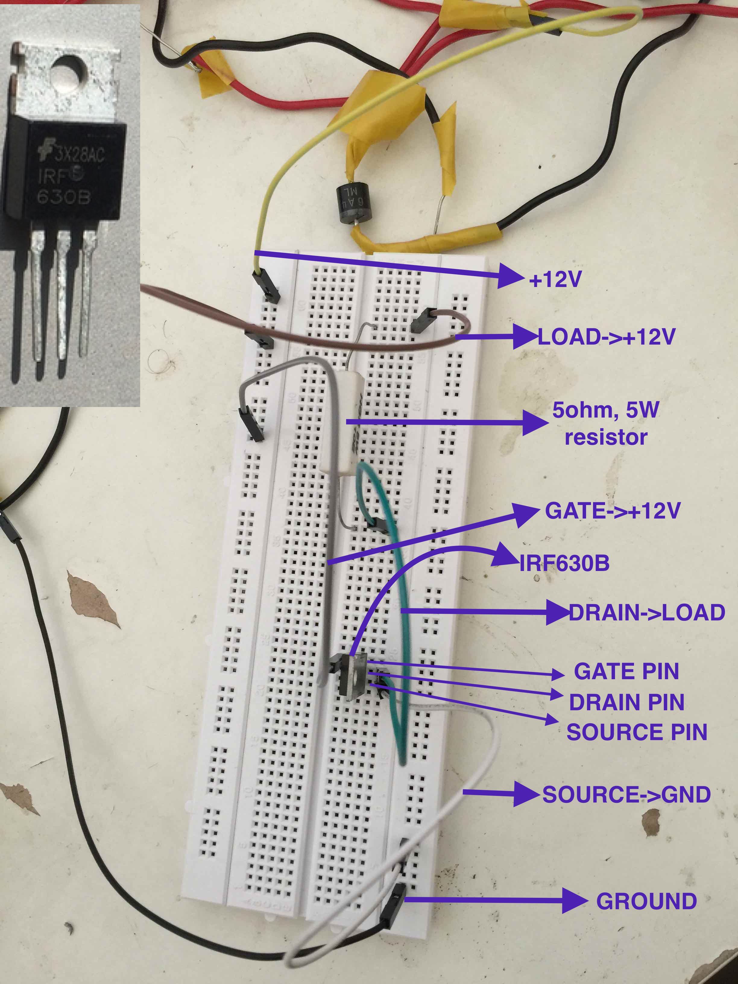
Q2. What am I doing wrong? breadboard with ohmic load no load

\$\endgroup\$
13
  • 1
    \$\begingroup\$ Related question. \$\endgroup\$ Commented Oct 23, 2015 at 10:41
  • 1
    \$\begingroup\$ Better use use a more-or-less ohmic load: better predictable behaviour. \$\endgroup\$ Commented Oct 23, 2015 at 12:00
  • 1
    \$\begingroup\$ What do you get on your meter if you measure a 0.5ohm resistor? \$\endgroup\$
    – user1844
    Commented Oct 23, 2015 at 12:30
  • 1
    \$\begingroup\$ The Rds of 0.4 Ohm is measured with 5A pulsed drain current (according to the datasheet). It will be higher at lower currents. What are the details of your motor is it a brushed or brushless DC motor? I'm surprised it takes 1.6A no load current - if that is what you mean by 'steady state draw'. \$\endgroup\$
    – Icy
    Commented Oct 23, 2015 at 13:08
  • 1
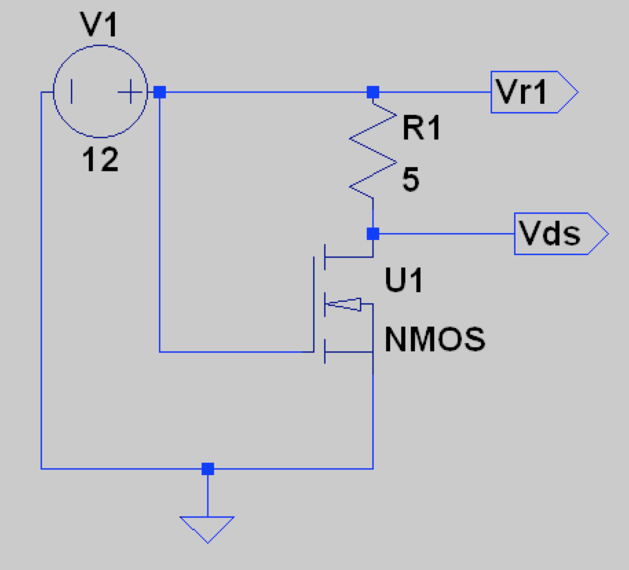
    \$\begingroup\$ @Wouter, I added a 5ohm, 10w resistor between +12v and the drain (updated schematic in the main post). I measured the voltage Vr1 (across the resistor) and Vds (across drain and source). Vr1 started at 3.4 and kept falling and Vds started at 7.8 and kept climbing. I monitored till 3.2Vr1/8.1Vds and stopped since the mosfet was getting too hot. To me it seems that the mosfet is simply not biased right, Id wont cross 0.6amps and Rdson wont fall below 10-12ohms. What can I do to fix it? \$\endgroup\$ Commented Oct 23, 2015 at 15:12

4 Answers 4

1
\$\begingroup\$

I can't answer questio 2n since my computer got a problem and I can't see your schematic but I can answer question 1:

Q1. Am I measuring the Rdson correctly? (it does not need to be accurate, good approx is enough)

Answer: No you don't. A multimeter is not meant to measure a resistance if there is current flowing through it. The resistance measurement need to be done without power on the board.

If you want to measure Rdson you can do the same operation but putting your multimeter in voltage mode. You measure the voltage between the drain and the source. With another multimeter you measure the current flowing through the transistor. then You do R = U/I and you have your Rdson.

\$\endgroup\$
1
  • 2
    \$\begingroup\$ His schematic shows trying to measure resistance of Drain-Source with multimeter - only current through this path would be from the multimeter. 12V is applied between gate and source. \$\endgroup\$
    – Icy
    Commented Oct 23, 2015 at 13:14
1
\$\begingroup\$

Direct in-circuit resistance measurement with a regular 2 wire multi-meter is not possible. You need to measure voltage and current separately and do the calculation. because this is a very simple circuit, I suggest you to first make sure 12V is really 12V (measure the source voltage). then make sure the R1 is really 5 Ohm (measure the resistance). then run the circuit and measure the Drain Voltage. it should be around 0.9V (assuming the RDS=0.4 Ohm as Datasheet says).

1) Measure the Drain Voltage: V(Drain)
2) Calculate the current: I(R1) = I(Drain) = [12V - V(Drain)]/R1
3) Calculate the channel resistance: Rds = V(Drain)/I(R1)

\$\endgroup\$
2
  • 1
    \$\begingroup\$ pls refer my response to Wouter above. V is actually an output from a SMPS supply, so I think its ok. I checked up the resistance as well. \$\endgroup\$ Commented Oct 23, 2015 at 17:25
  • \$\begingroup\$ The FET is not really "in the circuit". Only the gate and source are connected and no current is flowing. \$\endgroup\$ Commented Nov 23, 2016 at 2:09
0
\$\begingroup\$

The circuit you have will not allow you to measure \$\text{Rds(on)}\$. The MOSFET goes into saturation when two condition are true: $$ V_{GS} > V_{Th} \\\text{and} \\ V_{DS} \ge \left(V_{GS} - V_{Th}\right) $$ The first condition is true for your multimeter circuit. However, since the drain is floating the second condition is not satisfied. Connecting the multimeter in resistance mode between the drain and source will bring the drain to a voltage close to the source. The second condition is definitely not satisfied. The MOSFET is in the linear region, and one would expect the \$\text{Rds(lin)}\$ to the bigger than \$\text{Rds(on)}\$.

In order to measure \$\text{Rds(on)}\$, you would need to use the first circuit you posted, where the drain is connected to the power supply through the resistor. This will keep the drain positive enough to allow the MOSFET to go into saturation.

However, you can't measure the resistance of the MOSFET directly while it's in the circuit. The best way to measure \$\text{Rds(on)}\$ is to use the multimeter to measure the voltage and current and use Ohm's law to determine \$\text{Rds(on)}\$.

Edit: You can calculate the current by measuring the voltage across R1

\$\endgroup\$
6
  • \$\begingroup\$ Ok. However, as you can see in my comment above, using the first circuit does not drive the mosfet into saturation. Rdson using ohms law seems to be in the range of 10-12 ohms. \$\endgroup\$ Commented Oct 23, 2015 at 17:43
  • \$\begingroup\$ What were your measurements for Vds and Vr1? \$\endgroup\$ Commented Oct 23, 2015 at 17:59
  • \$\begingroup\$ Vr1 started at 3.4 and kept falling and Vds started at 7.8 and kept climbing. I monitored till 3.2Vr1/8.1Vds and stopped since the mosfet was getting too hot. To me it seems that the mosfet is simply not biased right, Id wont cross 0.6amps and Rdson wont fall below 10-12ohms. \$\endgroup\$ Commented Oct 23, 2015 at 18:01
  • \$\begingroup\$ Yes, one of the first things I checked. Using details from datasheet, I tested the presumed gate pin. Controlling this pin controlled the conductivity across two other pins. \$\endgroup\$ Commented Oct 23, 2015 at 18:13
  • 1
    \$\begingroup\$ Terminology confusion between in circuit use and device definition, possibly? Device definition has saturation as Vds>(Vgs-Vth), but that's the constant current operating region. To see Rds needs the defined linear region when Vds<(Vgs-Vth). Can seem like a confusing contradiction, I know, but there it is. \$\endgroup\$
    – user16497
    Commented Oct 24, 2015 at 17:34
0
\$\begingroup\$

It could be oscillating. Have you looked at Gate and Drain with a scope?

Looking at the breadboard photo, there is a huge loop for the Gate circuit. Wire loop inductance is roughly:

\$L\$ ~ \$\mu_o\$ \$\pi d\$

If \$d\$ is about 0.2m, then \$L\$ is about 800nH. Put that with ~800pF for \$C_{\text{iss}}\$, gives \$Z_o\$~32\$\Omega\$, and \$f_o\$~8MHz. This would be a pretty high Gate Q. Coupled with \$R_1\$ of 5\$\Omega\$ and \$g_{\text{fs}}\$ of 7S, \$C_{\text{gd}}\$ would act like ~1000pF. Also, \$L\$ could be higher, it's hard to tell how far the wire extend out of the photo. It would seem a good case for oscillation.

You might try putting about 100\$\Omega\$ in series with the Gate to dampen things out.

\$\endgroup\$
6
  • \$\begingroup\$ Tried this, but results are same. The power supply is not too far off, 0.2m seems like a good assumption. Whats not clear to me is why Vds keeps climbing (instead of falling). \$\endgroup\$ Commented Oct 24, 2015 at 17:47
  • \$\begingroup\$ @Vijay As temperature increases, gfs will decrease and Rds will increase. Both will tend to make Vds increase, until failure. Did you look at it with a scope? Have you tried multiple parts to make sure it's not just a bad or damaged FET? \$\endgroup\$
    – user16497
    Commented Oct 24, 2015 at 18:13
  • \$\begingroup\$ Am just a hobbyist, dont have access to a scope. I bought about 10 FETs and tried all of them for tests described in the other comments in this post. The sense I got from my research is that Iam not bringing the mosfet out of the power dissipating zone fast enough. But I cant figure out what else I can do (other than the stuff described in this post) \$\endgroup\$ Commented Oct 24, 2015 at 18:18
  • \$\begingroup\$ @Vijay Your circuit should work. Concept is fine. Oscillation or damage is the only thing that seems reasonable. As long as you are not trying to switch rapidly, you could improve gate circuit by placing a capacitor (~0.1uF) from source to gate (closely), but with 100 Ohm between cap and gate. The cap would decouple inductive wires from gate, while resistor reduces Q of gate and cap. \$\endgroup\$
    – user16497
    Commented Oct 24, 2015 at 18:25
  • \$\begingroup\$ @Vijay With R1 of 5 Ohms, heat rise of FET will be about 140C, which is high for the FET (and also the poor 5 Ohm resistor). It would be best to lower drain current by changing R1 to 500 or 1000 Ohms. Then heat could be eliminated as a problem. \$\endgroup\$
    – user16497
    Commented Oct 24, 2015 at 18:42

Your Answer

By clicking “Post Your Answer”, you agree to our terms of service and acknowledge you have read our privacy policy.

Not the answer you're looking for? Browse other questions tagged or ask your own question.