6
\$\begingroup\$

I am trying to get a 3.3V voltage from 5V (2A) power supply to power my Arduino Pro Mini 3.3V.

I am using LD1117 3.3V Regulator (TO-220). I haven't connected any coupling capacitor as the datasheet suggested yet. I just connected the Vin and measure the output Vout on pin 2.

The problem I am facing is that, I think I am burning up the regulator because on Vout, I am measuring almost 3A current output. The regulator is very hot!

I read that LD1117 regulator is able to output 800mA max and please correct me if I am wrong but I think my Arduino Pro Mini can work pretty well with just 800mA. I am also hooking it up to a RFM89HW transceiver.

Questions:

  1. How can a 2A power supply output 3A current? I don't understand the logic, output more than input?
  2. How do I limit the input current so I don't burn out my regulator? 800mA outuput current is fine.

Thank you for your time.

Edited (added circuit)

enter image description here

\$\endgroup\$
6
  • 2
    \$\begingroup\$ Circuit please. It sounds like that if you are measuring 3A at the output, you are using an ammeter and short circuiting it, rather than a voltmeter on an open circuit. Most supplies have a rated current, that they can do all day without frying, and then have a current limit set a little above that to protect themselves, 2 to 3A sounds a reasonable spread for that. \$\endgroup\$
    – Neil_UK
    Commented Oct 26, 2015 at 7:02
  • \$\begingroup\$ Hi user44635. Yes, I measured it using a multimeter directly as my diagram above shows. Am I doing it wrong? \$\endgroup\$
    – maomaopop
    Commented Oct 26, 2015 at 7:23
  • \$\begingroup\$ Set your multimeter to Voltage. \$\endgroup\$ Commented Oct 26, 2015 at 7:30
  • \$\begingroup\$ If I set it to Voltage, I get 3.3V. \$\endgroup\$
    – maomaopop
    Commented Oct 26, 2015 at 7:40
  • \$\begingroup\$ Where is your LD1117 in this diagram? I only see a LM78xxL. \$\endgroup\$ Commented Oct 26, 2015 at 10:09

3 Answers 3

16
\$\begingroup\$

You've got a few misconceptions. But don't worry, many people get confused by these principles when they're first learning about electronics. I'll try to clear up the misconceptions and answer your specific questions at the same time:

1) A regulator that advertises 800mA means it can output up to 800mA without burning up. It does not mean the the regulator will automatically limit the current to 800mA. Nor does it mean it will always provide 800mA to any load. It is simply stating the maximum safe current the regulator is capable of. Under normal circumstances, your circuit load should be using far less than the maximum. Otherwise, you need a bigger regulator.

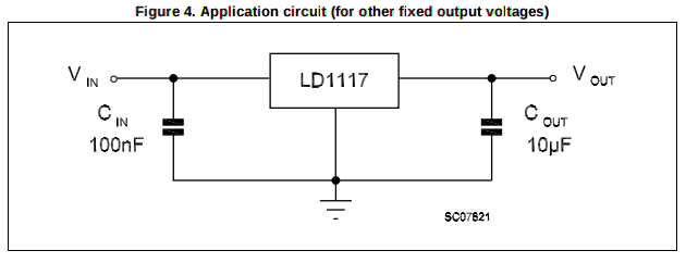
2) The LD1117 is a linear regulator. These types of regulators must have appropriate capacitance on the inputs and outputs. Otherwise, the output may oscillate and cause any number of problems downstream in your circuit. It will also cause the reading on your multimeter to be wrong without you knowing. The datasheet for your part will tell you how much capacitance and what type (ceramic, aluminum, etc) to use. Here's a screen capture of the recommended circuit from STMicroeletronic's LD1117: enter image description here
3) From your fritzing diagram, it looks like you used the ammeter function on your multimeter incorrectly. Ammeters are designed to appear "invisible" in your circuit. That means the circuit will act as if the ammeter was just a piece of wire. You connected the 3.3V output of the regulator, through the ammeter, to ground like this:

schematic

simulate this circuit – Schematic created using CircuitLab

Since the ammeter acts like a piece of wire, this schematic is equivalent to:

schematic

simulate this circuit
See the problem? You've got the 3.3V output directly shorted to ground! The reason you're only seeing 3A is because the internal components of the regulator are overheating and acting like resistors. If the LD1117 was a little more beefy, it would be outputting a lot more than 3A. In fact, if the regulator were an ideal voltage source, your current would be infinite! The appropriate place to put the ammeter is here:

schematic

simulate this circuit

4) It is not up to you, the circuit designer, to "limit the input current" to the load. The load (the Arduino) will draw as much current from the regulator as it needs to function at any given time. And that current draw will change as the Arduino does different tasks. In fact, if you attempt to implement a current limiter, it will likely cause a brown-out and the Arduino will reset or lock up.

It is unlikely that an Arduino will need more than 800mA to do anything, so that regulator should be fine. Under typical circumstances, a development board like an Arduino should only draw in the 10s or low 100s of mA.

So if the regulator is overheating, there are two possibilities:

a) The regulator you chose can't handle the current draw of the load. For example, if you were trying to power 50 LEDs that are rated at 20mA, your LD1117 would overheat trying to push the 1A of current. In this case, you would need to choose a regulator with a higher current capacity.

b) Something is shorting to ground or pulling more current then it should. You've experienced this by shorting the regulator output to ground through your multimeter's ammeter function. It could also happen with a misplaced wire, an unintentional solder bridge, or a bad component.

The problem you're having is obviously (b) above.

\$\endgroup\$
5
  • 2
    \$\begingroup\$ OMG! Now I understand the meaning short to ground. Lucky I didn't fry my PSU or the regulator. Thank you so much Dan Laks, very helpful with all the diagrams and examples. A+ answers! \$\endgroup\$
    – maomaopop
    Commented Oct 26, 2015 at 9:15
  • \$\begingroup\$ @mmk Don't worry, regulators like this have an overtemperature cutout that will turn them off if they overheat. Also, note that 800mA is an upper limit: if you had 15V input and 1.5V output (for example), it's not going to be able to do 800mA without a heatsink! \$\endgroup\$ Commented Oct 26, 2015 at 9:35
  • \$\begingroup\$ nice answer. I'd also recommend making sure you have the correct datasheet for your specific 1117 component. For example, the ST LD1117 has TO-220 pins gnd-out-in, but the UTC LD1117 TO-220 is in-gnd-out. I've connected a UTC per the ST pins before, and without load the first thing I notice is the device quickly gets very hot (thankfully disconnected without damage) \$\endgroup\$
    – tardate
    Commented Oct 26, 2015 at 13:24
  • \$\begingroup\$ Nick Johnson, I have a heat sink but I think I need to better my power efficiency circuit. My understading is that if it is too much heat, I am wasting power. I want to build a wireless Arduino end-node and I want to conserve as much power as possible because it is going to run battery. I am awaiting for my AMS1117 module from ebay, will try that later. \$\endgroup\$
    – maomaopop
    Commented Oct 26, 2015 at 14:53
  • \$\begingroup\$ tardate, my LD1117 pinout is Gnd-out-Vin. Hehe, confirm working because I can get 3.3V output. \$\endgroup\$
    – maomaopop
    Commented Oct 26, 2015 at 14:54
0
\$\begingroup\$

You are measuring the short circuit current of your supply and of your regulator. You are lucky that at least one of the supply has a current limit to prevent a very large current being drawn which would destroy your device at once.

Measure the open circuit output voltage on a volts setting, after you've added the other capacitor components that the manufacturer's circuit requires. Without them, it may oscillate, making a voltmeter measurement meaningless. This gives you the voltage, hopefully 3.3v, that's available to your downstream circuit.

Put your ammeter in series with the regulator output, and connect the load between the other ammeter termial and ground. This gives you the current that your load takes, You would expect a 6.6ohm load to take 500mA for example.

\$\endgroup\$
2
  • \$\begingroup\$ Yes, I get 3.3V if I set it to voltage. Ok, I will install coupling capacitors to it. Are you saying that, it is ok that my LD1117 regulator to receive 5V (2A) power supply? It will only output maximum 800mA once I add my Arduino load? The heat I presumed is normal and I should a heat sink to the regulator? I am really new to electronic and sorry if I ask simple question. \$\endgroup\$
    – maomaopop
    Commented Oct 26, 2015 at 7:44
  • \$\begingroup\$ @mmk It will only output a maximum of 800mA if the load draws that much. I would expect an Arduino to draw much less. \$\endgroup\$
    – Neil_UK
    Commented Oct 26, 2015 at 14:06
0
\$\begingroup\$

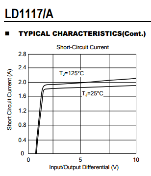
ST's datasheet on LD1117 is rather lacking info on short-circuit behavior, but UTC's clone/variant does show the short circuit current is around 1.8-2.2A (and varies with the temperature and input-output voltage difference)

enter image description here

I suppose ST's could go to 3A (when it heats ups), but there's no relevant info that I can find in their datasheet.

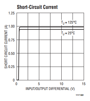
Also LT's variant of this regulator, i.e. LT1117 limits the short-circuit current to a saner value of 1A (saner relative to max normal operating condition of 800mA)

enter image description here

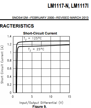
TI's limit current for their LM1117 is about 1.2-1.3A:

enter image description here

Moral of this [part of the] story is: if you want to rely on the regulator to limit current you need to read its datasheet carefully... Even for near-clones like this 1117, there can be substantial differences between manufacturers.

As for

How do I limit the input current so I don't burn out my regulator?

The regulator won't burn [easily] because of its built-in over-temperature protection. (You need to worry more about what it is feeding with its high short-circuit current.)

But if you want to limit the current more precisely, look up "precision current limiter" "adjustable current limit" and similar terms; some regulators come with these built-in, but they are 5-pin regulators, e.g. LT1185, NCV47701. You can also add separate ICs that do mostly just that (current limiting), e.g. LTC4415 (that's an ideal diode, also prevents backfeeding and incorrect/inverse source connections), or build your own with discretes.

\$\endgroup\$
1
  • 1
    \$\begingroup\$ Thank you Respawned Fluff. Your answer is helpful. I think my questions are not accurate, initially I thought 2A input is too much current because LD1117 has maximum current output of only 800mA. So I thought of limiting it. However as Dan Laks pointed out my misunderstanding, it doesn't really matter because it depends on my load. As long I don't draw more than 800mA and above, it won't fry my regulator. It is overheating because I am shorting it to ground. Haha. \$\endgroup\$
    – maomaopop
    Commented Oct 26, 2015 at 14:23

Your Answer

By clicking “Post Your Answer”, you agree to our terms of service and acknowledge you have read our privacy policy.

Not the answer you're looking for? Browse other questions tagged or ask your own question.