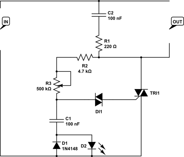
I recently bought a DIY 1000W AC motor dimmer meant to be powered off 220-240VAC. I was hoping to use this to control a transformer which in turn powers a heating element.
The heating element needs 60W and i think the resistance is about 5mOhm. My derivation of this is at the bottom. Rather than try get the windings on the transformer perfect i thought using this dimmer control would give me enough flexibility.
This is the circuit that has been supplied:

simulate this circuit – Schematic created using CircuitLab
I am new to triac and diacs but my first question is more about the 1000W rating on this circuit. With my heating element only needing 60W is it a good idea to change the values for some of the resistors and/or caps? or is this 1000W just an absolute max with no relevance to the magnitude of control i would get with a lower powered load?
Secondly, the terminals were not labelled on the diagram and are not labelled on the PCB either. If somebody could figure out the orientation of the IN and OUT terminals i would greatly appreciate it.
Deriving Resistance of the heating element:
- Connected the element in series with a 100 (99.3)Ohm resistor powered by a 4 (3.965)V supply.
- Measured the voltage drop over each of them
- Over element \$V_e = 0.2mV\$
- Over resistor \$V_1 = 3.94V\$
- \$ R_e=V_e * R_1/V_1 =5.05 mOhm \$
the 0.2mV drop over the element is very close to the minimal 0.1mV that my DMM is able to measure so i do not know how accurate it is. If anyone knows a better way to test the resistance please let me know.
