0
\$\begingroup\$

I am trying to amplify a CT sensor. The sensor is giving 5mV amplitude for low current, 100mV amplitude for higher current.

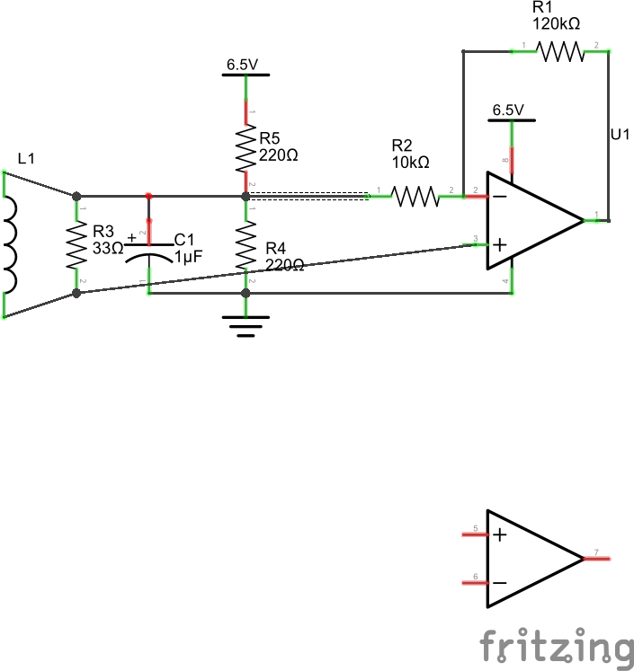
I built a voltage divider with 220 ohm resistors, and connect to a noninverting opamp with gain that should be 120k/10k+1 or about 13.

I am using 6V battery packs for positive and negative power for the LM358. The waveform going into the op amp shows on the oscilloscope as 5mV amplitude @60Hz.

The waveform coming out is only positive, and there is no gain. Since I'm fairly sure I built the circuit correctly, I'm first showing the schematic, assuming that the concept is wrong. If you experts tell me the schematic is right, then I will have to take a picture of the circuit and attach it to determine how it is built wrong.

enter image description here

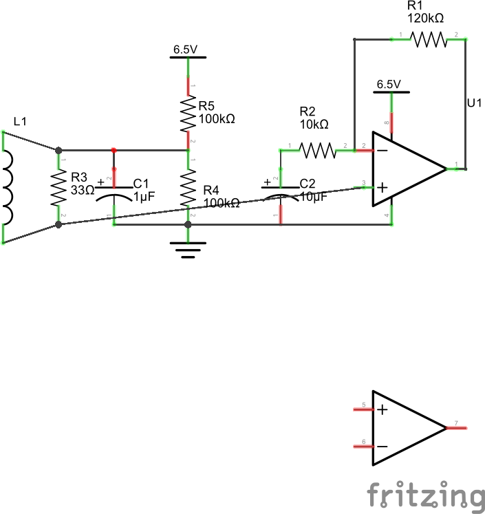
Ok, in light of the answer I am posting a revised corrected schematic enter image description here
\$\endgroup\$

2 Answers 2

1
\$\begingroup\$

I can offer you some simple changes that should improve things for you.

1) Change R4 & R5 to 100k. Leave C1 as 1uF.

2) Disconnect the left end of R2 from the junction of R4 & R5 and instead connect the left end of R2 to the positive side of a 10uF capacitor. The negative side of the capacitor goes to ground.

These changes separate the virtual-earth node (junction of R4, R5, C1) from the feedback network.

I'm also assuming that you are running the op-amp from a single, positive supply with the negative rail pin of the chip grounded. Please let us know if that is NOT the case - the circuit does change if you are using a bi-polar power supply.

\$\endgroup\$
2
  • \$\begingroup\$ He can use DC coupling by connecting R4-R5 midpoint to OA+ and to one side of CT and other side of CT to R2.At present the 33R is shunting the lower 220R and ground referencing the CT rather than midpoint referencing it. \$\endgroup\$
    – Russell McMahon
    Commented Nov 25, 2015 at 12:10
  • \$\begingroup\$ This was it! Terrific. I am going to edit the question showing the new schematic. \$\endgroup\$
    – Dov
    Commented Nov 26, 2015 at 1:18
0
\$\begingroup\$

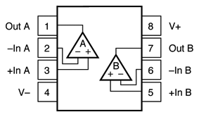
This is how you wire power to a dual op-amp: -

enter image description here

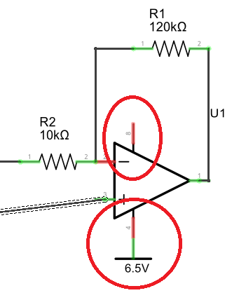
You appear to have +6.5 volts connected to pin 4 (normally neg supply or ground) and nothing connected to pin 8 (requires Vcc): -

enter image description here

\$\endgroup\$
2
  • \$\begingroup\$ Sorry, the schematic is sloppy. I have power connected correctly \$\endgroup\$
    – Dov
    Commented Nov 25, 2015 at 13:32
  • \$\begingroup\$ Then you need to explain how you have it connected and also confirm what op-amp you are using. I have only your words and a circuit and the circuit is wrong therefore it is totally reasonable to assume you don't know how to do this so, please fully describe how you are powering the op-amp. \$\endgroup\$
    – Andy aka
    Commented Nov 25, 2015 at 13:53

Your Answer

By clicking “Post Your Answer”, you agree to our terms of service and acknowledge you have read our privacy policy.

Not the answer you're looking for? Browse other questions tagged or ask your own question.