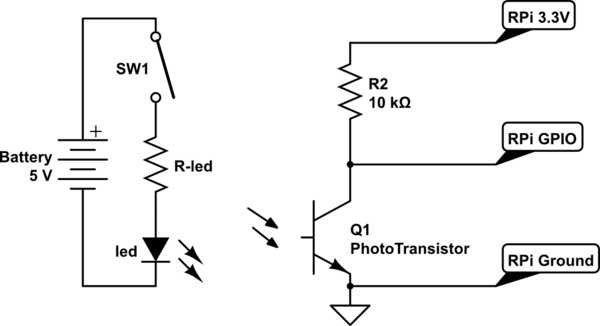
Please help:
I am building a photogate. I was looking for help in building a circuit for the Raspberry Pi 2.
A little background:
I am still a highschool grade 12 student! and I have a basic understanding of circuits as we have not even started electronics and so that is why, I absolutely have no idea how phototransistors change current and so that is why, I have no idea what would the answer be. Also, I am semi sure of how multiple branches affect the current and voltage and resistance. Sorry! I am building this for my Physics IA. Going a little stronger. I will appreciate help or the circuit but if possible, I will appreciate any form of knowledge I can gain.
Design objectives:
What I am looking to build is a simple circuit which has one lead going to input of the GPIO board. One lead to ground and one lead to either 3.3V or 5.0V on the GPIO board, I have no idea how to select which voltage to use. The circuit would have a ir phototransistor that when dark would give an input in raspberry pi GPIO input of 2.0 volt-3.3 volt and 0.0v-1.0 volts when light. I can use any resistor. I want to build the most basic circuit that can give me these inputs when dark and when light. Thanks A lot. Please ask for clarification if needed.
PS. this is a question to build a circuit whereas the other question is about input values from a pre-existing circuit.

