I need a VERY simple latching circuit using a comparator that will simply be off until a signal hits it (can be either + or -, I have no preference). The circuit should remain on until I reset it.
5 Answers
You could do something like this- the comparator output goes low when the input passes +2.50VDC (the voltage set by the R3/R3 resistor divider, which turns on the LED D1 and also Q1. Q1 pulls the inverting input up to +5 regardless of the voltage at the input so the LED will not turn off. SW1 shorts out the transistor drive so the LED will turn off and, if the input voltage is less than 2.5V, will stay off when the switch is released. Otherwise it will come on again immediately when the switch is released.

simulate this circuit – Schematic created using CircuitLab
-
1\$\begingroup\$ pefhanny: Thank you.I build this circuit and it works fine. \$\endgroup\$– NewbieCommented Dec 8, 2015 at 10:21
With a comparator and a D-flipflop (74hc74) use the output of the comparator (with a pull-up resitor) as flipflop CLK. Set the flipflop D=1, S=1, and use R as reset. The output of the flipflop Q is the Latched output.
-
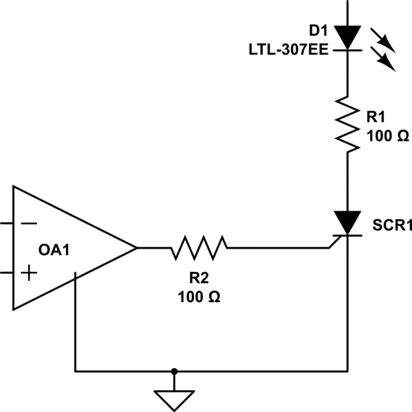
\$\begingroup\$ You can use only a comparator and thristor at output, then when power off (or disconnect thyristor only) it will reset. \$\endgroup\$ Commented Dec 1, 2015 at 19:39
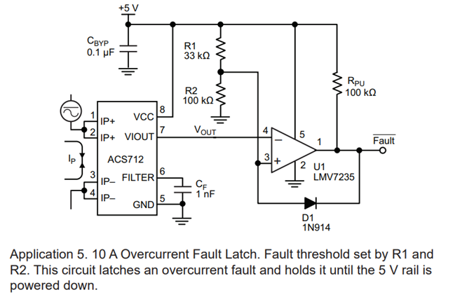
with a bit of positive feedback it's easy to make a comparitor latch.

simulate this circuit – Schematic created using CircuitLab
-
\$\begingroup\$ where's a switch (or other means) to reset it? \$\endgroup\$– tcrosleyCommented Dec 2, 2015 at 2:55


