I am trying to create an 8 digit, 7 segment display using an Arduino, 2 4-digit displays and an 74HC138 demux. The 4 displays each have 12 pins: 4 common cathodes, 7 segments and one dot. I thought I would use 8 of the Arduino's digital pins and wire them to the segment and dot pins on the displays, and then use the of the Arduino's digital outputs to control the 74HC138 demux and use that to select the subdisplay. The IC outputs a LOW on the output pin, and so I need to wire a transistor so that it connects the common cathode to ground only when the base current is LOW. Is that correct? How would I wire the components to do that and what transistor do you recommend for this? Should I add any resistors between Arduino's +5V and the LED displays or the IC output and the base terminal of the transistor?
2 Answers
Using an external decoder for digit selection is a good idea, since it will save on Arduino pins (but you'll still need 3 address pins). And you are correct that you'll need boost transistors. Connecting a decoder with active-low outputs, like a 74HC138 to transistors to provide active-low display drive is not exactly simple for beginners, since you'll need 2 transistors per channel. You can do it like this

simulate this circuit – Schematic created using CircuitLab You'll notice that it takes 2 layers of function. Since you're already buying a decoder, you can save some circuitry if you instead use the 74HC238. This is identical to the 138 except that the outputs are active high, and you can do this

simulate this circuit instead. Using the components shown, you'll have no trouble drawing 50 mA per cathode, and 100 mA is entirely reasonable.
-
\$\begingroup\$ The 2N3906 is a PNP transistor, right? I'm not entirely familiar with how PNP transistors work, I am much more used to NPN's... As for the 138, that is what my local electronics store provides, it took half an hour of googling to find an IC that is both a demux and in stock at the local store :D Unfortunately, they do not seem to stock the 238. Any suggestions? \$\endgroup\$ Commented Dec 18, 2015 at 21:26
-
\$\begingroup\$ Try digikey.com. And PNPs are just like NPNs, except that you tie the emitter high, and pull base current rather than sourcing it, and the collector sources current instead of sinking it. \$\endgroup\$ Commented Dec 18, 2015 at 21:56
-
1\$\begingroup\$ There's also the venerable ULN2002/3/4 containing 7 driver transistors in a single DIP. That could be interesting if you want to breadboard this and don't want to connect everything. \$\endgroup\$– pipeCommented Dec 18, 2015 at 22:11
-
\$\begingroup\$ Apparently they have ULN2003/4's in stock :) Exactly what are they and how could I use them to replace the two transistors in the above schematic? \$\endgroup\$ Commented Dec 19, 2015 at 6:31
-
\$\begingroup\$ @andreas.vitikan all electronic components have a datasheet associated with it that describes thevpart and cover the specification of the part. More often than not will include application information and reference schematics. ULN2003 datasheet \$\endgroup\$– crasicCommented Dec 21, 2015 at 18:46
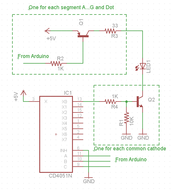
In addition to the cathode drivers you will also need buffers for the 8 Arduino digital pins that are used for the Anodes.
Based on the LED display data sheet you may want to drive each segment with 10mA. Since each display digit is only driven 1/8 of the time you have to drive it with approximately 8 times as much current (80mA) to get an equivalent brightness.
Q1 only has to drive one LED at the time so a 2N3906 might be good enough.
Q2 has to be able to handle the current for all the segments in one digit, 7 + dot = 8. If you use 80mA per segments as an example, this means this transistor should be able to handle 8 x 80mA = 640mA.
The CD4051 is a multiplexer that may be an alternative to the 238 that was suggested in another answer.
An easier solution may be a Maxim MAX7219. It greatly simplifies the design and has a lot of functionality. You can use the Arduino's SPI bus to control it.
https://www.maximintegrated.com/en/products/power/display-power-control/MAX7219.html
Some Arduino related stuff can be found here: http://playground.arduino.cc/Main/LEDMatrix
-
\$\begingroup\$ What exactly do you mean by a buffer? \$\endgroup\$ Commented Dec 19, 2015 at 6:30
-
\$\begingroup\$ If reduced brightness would be acceptable, limiting current to an amount that the display can tolerate for hours on end will avoid having a display get destroyed by software malfunctions. If one would want to use higher currents, it may be good to add hardware circuitry to ensure that no digit driver can be on for too long at once. \$\endgroup\$– supercatCommented Dec 21, 2015 at 17:52

