5
\$\begingroup\$

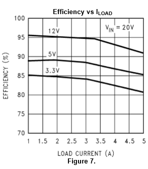
I'm working with a TI LM2678-ADJ regulator (granted, on a breadboard) to power a 40" led strip. Trying to figure out why the measured efficiency is about ~15% lower than what the charts in the datasheet claim.

Input: Vin = 20V, Iin = 0.925A (18.5W*)

Output: Vout = 12V, Iout = 1.255A (15.06W*)

*Didn't measure power directly, but using V x I to calculate power based on measured V and I.

So given those values it would seem the efficiency (Pout/Pin) is about 81.4%.

But the chart in the datasheet claims it should be about 95% efficient: enter image description here
For refecence here the schematic from the datasheet: enter image description here
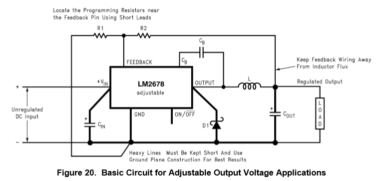
Could the ~15% discrepancy be attributed to the other components in the circuit? I'm not using exactly the recommended components from the datasheet but at least similar spec'd ones (from what I can tell).

This is the inductor I'm using: http://www.digikey.com/product-detail/en/2107-V-RC/M8852-ND/775391

\$\endgroup\$
0

2 Answers 2

3
\$\begingroup\$

Things that can likely go wrong: -

  • Building it on breadboard - contact resistance versus solder
  • Building it on breadbaord - contacts/track volt drops
  • The inductor gives no clue to how it will perform at 260 kHz - choose one that does
  • 33uH is probably not the best choice - 47uH is a better choice for 20V in and up to 2A out (assumed LM2678-12 and adjustable version)
  • Bad positioning of input and output capacitors
  • Bad choice of input and output capacitors (electrolytics are quite possibly a bad choice so follow the data sheet as to its recommendations - it has many)
  • Inductor leads too long
  • Measurement errors in meters
  • Measurement errors in probing
  • Schottky diode of correct type not used (DS says: From Table 10 a 5A or more Schottky diode must be selected)

Breadboard build is the worst culprit. Trust that it will work, lay out a PCB, come back here and get someone to review the layout. Don't build switchers on BB.

\$\endgroup\$
2
\$\begingroup\$

Did you run your part through the online WebBench tool that TI has at their web site? That tool lets you pick alternate components and will show the resulting efficiency.

Your selection of components different from what TI uses in their simulations and data sheet preparation can have a big impact on the efficiency achieved. Some examples that would lower efficiency could be selection of a flyback diode with higher forward voltage drop, selection of a inductor that has a higher DC resistance, selection of input capacitors that have higher ESR or lower ripple current ratings, or improper selection of the CB capacitor so that optimum boost voltage is not achieved.

Component placement and routing can also have an impact on the efficiency that can be achieved. For example very best performance you need the switch node between the IC, diode and inductor to be as small/short/isolated as possible.

\$\endgroup\$

Your Answer

By clicking “Post Your Answer”, you agree to our terms of service and acknowledge you have read our privacy policy.

Not the answer you're looking for? Browse other questions tagged or ask your own question.