0
\$\begingroup\$

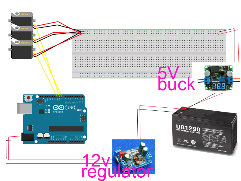
I am trying to control 8 servo's with an arduino uno using ROS. The diagram below shows my current configuration to power the servos. I have a buck regulator in between the 12v battery and the breadboard.

The arduino is powered thru a barrel plug which goes into a 12v regulator which connects to the 12v battery.

This does not seem to work when I have many servos. Strange things happen when I try to manipulate all 8 servos at once, a few respond but most do not. Also they all seem to get jitters and wobble while plugged in.

Why is that? Also what is the best way to power up and use many servos?
I planned on using the arduino mega 2560 to manipulate up to 30 servos. enter image description here buck 5v:
Module Properties: Non-isolated step-down module (buck).
Rectifier: Non-Synchronous Rectification.
Wide Input voltage: DC 4.5-40V.
Output Voltage: DC 1.2-37V (Adjustable) (output voltage from the USB = output voltage from the output port ).
Output current: rated current 2A, 3A MAX (Additional heatsink is required).
If you need its output power greater than 2A/10W, please add with heat-sink.
Short circuit protection: current limiting, since the recovery.
Operating temperature: Industrial grade (-40 to +85 )
Load regulation:±0.5%
Voltage regulation:± 2.5%
No CC, current display function

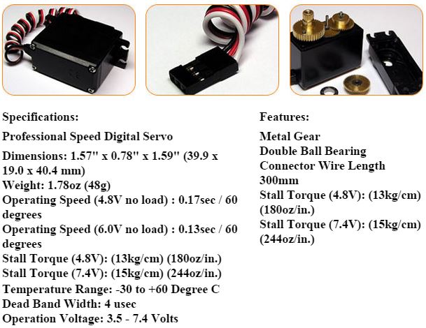
each servo: enter image description here

\$\endgroup\$
10
  • \$\begingroup\$ More than likely the 5V buck can't provide enough current. We can't answer this without specifications for the servos and buck converter. Please edit the question and include the details. \$\endgroup\$
    – Transistor
    Commented Dec 24, 2015 at 16:27
  • \$\begingroup\$ @transistor thank you, please let me know if the revised question is sufficient. \$\endgroup\$
    – t q
    Commented Dec 24, 2015 at 16:32
  • \$\begingroup\$ Excellent. We're missing one piece of information - the stall or start current for the motor. Can you measure either the motor resistance (which we will use with Ohm's law to work out the max current) or measure the current drawn by one servo while you stall it during a commanded move. If we can work out the worst case current drawn be one servo we can see how many you could simultaneously move with your PSU. \$\endgroup\$
    – Transistor
    Commented Dec 24, 2015 at 16:38
  • 2
    \$\begingroup\$ Sometimes the power rails along the sides are interrupted (by design) somewhere half way. \$\endgroup\$
    – jippie
    Commented Dec 24, 2015 at 18:05
  • 1
    \$\begingroup\$ Consider using multiple regulators each handling a smaller number of servos. Also consider "battery eliminator" circuits (again, probably several) intended for use in model craft powered by 3 lithium polymer batteries, as such a pack has comparable voltage range to your input. Ideally group servos that won't move together (at least with high load) on the same regulator, and servos that will move together on different regulators. \$\endgroup\$ Commented Dec 25, 2015 at 3:46

2 Answers 2

1
\$\begingroup\$

From the information we have so far it appears that your buck converter may not be able to supply enough current to run all the servos simultaneously.

schematic

simulate this circuit – Schematic created using CircuitLab

Your general layout is good in that you have kept the power wiring separate from the motor wiring where the high currents could cause problems (such as burning out the PCB tracks or causing interference) if they ran back to the battery via the Arduino. The layout is poor because your are using the breadboard to carry relatively high currents. You should come up with a better way of connecting these.

The 12 V regulator between the battery and the Arduino isn't doing much. 12 V in, 12 V out. If anything I would reduce the output of this to, say, 8 V so there will be less heat dissipated in the Arduino voltage regulator.

Further updates as info comes in via chat room.

[Update]

From discussion in the chat rooms it appears to be a supply current problem. The buck converter hasn't enough oomph to power more than three or four servos under load.

\$\endgroup\$
2
  • \$\begingroup\$ I should remove the breadboard from the loop? \$\endgroup\$
    – t q
    Commented Dec 24, 2015 at 18:32
  • 1
    \$\begingroup\$ You're only using it as a terminal strip. Fine for tens of mA but not so good for hundreds. \$\endgroup\$
    – Transistor
    Commented Dec 24, 2015 at 18:39
1
\$\begingroup\$

If it isn't current limiting causing the servos problems then it's the horrible 0V scheme you've adopted. Try connecting the arduino's supply directly to the servos power feed because, at the moment, you have a very strong possibility of 0V bounce corrupting the control lines fed to those servos. Keep all wires as short as possible.

I see you cannot use the local supply to the servo so just reconnect the 0V as I've hinted.

\$\endgroup\$
6
  • \$\begingroup\$ I made an update to my wiring diagram, the arduino is powered by a barrel and regulator \$\endgroup\$
    – t q
    Commented Dec 24, 2015 at 17:06
  • \$\begingroup\$ You should have a direct connection between the arduino ground and the servo ground. \$\endgroup\$ Commented Dec 24, 2015 at 17:13
  • \$\begingroup\$ Why have you updated the wiring diagram? \$\endgroup\$
    – Andy aka
    Commented Dec 24, 2015 at 17:20
  • \$\begingroup\$ @Andyaka because originally it looked like I was powering from the usb, also I forgot to mention a regulator inbetween the arduino and 12v \$\endgroup\$
    – t q
    Commented Dec 24, 2015 at 17:52
  • \$\begingroup\$ @PeterBennett are you saying that there should be a ground connection from each servo to the arduino? \$\endgroup\$
    – t q
    Commented Dec 24, 2015 at 17:57

Your Answer

By clicking “Post Your Answer”, you agree to our terms of service and acknowledge you have read our privacy policy.

Not the answer you're looking for? Browse other questions tagged or ask your own question.