2
\$\begingroup\$

We have a project where our 2nd year students build an H-bridge controller from scratch. They learn a lot about power dissipation. We have a simplified design using IRF540 for the N-channel, IRF9540 for the P channel. These are way over-spec for the application, tiny robot motors. WE use 6V batteries, so to turn on the gate of the N-channel transistors we can use the output of the Arduino, and to turn on the gate of the Pchannel we set gate to 0V, or leave in a high-Z state with a pullup resistor.

This works. However, we were thinking of extending the exercise to show all N-channel. That's the way it's done at larger scale because the N-channel has such dramatically better on-resistance. I think the difference is 0.004 ohms vs. 0.113 ohms, so it's significant. This would require that we generate Vcc + 5V for the gate.

For a teaching circuit, with a power side of 12V, is there a simple, clean way to generate a tiny current at a voltage 5V higher than Vcc? We would like to have them build the circuit, not just use a black box.

\$\endgroup\$
5
  • \$\begingroup\$ What sort of gate drive frequency are you talking about? 1 Hz (turning on an off vehicle wheel motors to steer)? Or 20 kHz (PWM motor control)? \$\endgroup\$ Commented Dec 28, 2015 at 4:00
  • \$\begingroup\$ Definitely 20kHz, controlling vehicle speed. \$\endgroup\$
    – Dov
    Commented Dec 28, 2015 at 4:01
  • \$\begingroup\$ Out of curiosity, what's the success ratio for this H-bridge lab (the present version with P-channels on top)? \$\endgroup\$ Commented Dec 28, 2015 at 4:33
  • \$\begingroup\$ I think you might be looking for a dedicated gate-driver IC that integrates the charge-pump on-board, especially for a H-bridge application. I wrote my answer as such -- if it isn't what you're looking for, feel free to disregard. \$\endgroup\$ Commented Dec 28, 2015 at 7:43
  • \$\begingroup\$ I would probably rephrase the Heading for your question as "Designing a gate voltage converter for N-Channel MOSFETs for H-Bridge controller". As you don't generally design a voltage, but a means to get a voltage. \$\endgroup\$
    – crowie
    Commented Dec 28, 2015 at 7:45

4 Answers 4

2
\$\begingroup\$

5V is barely enough to turn on an IRF540. The specified 0.077 Ohms Rdson is achieved with 10V Gate drive. You are probably getting away with the lower drive voltage because your motors are only drawing a small current.

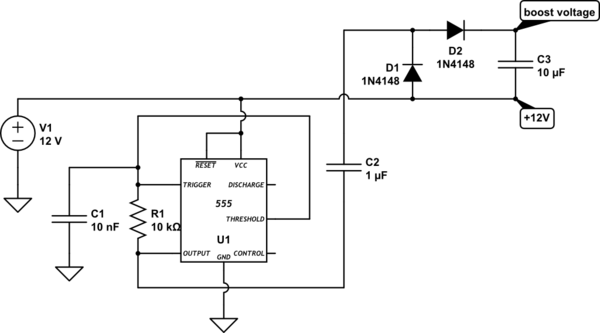
The simplest way to get a voltage higher than the supply is to make a 'charge pump' using a couple of capacitors and diodes. You also need a driving waveform with sufficient voltage and current, which could be produced by a 555 timer, CMOS gates, an op-amp etc. Here's an example circuit:-

schematic

simulate this circuit – Schematic created using CircuitLab

This circuit should produce about 22V (10V of boost) at 5mA. Note that this voltage exceeds the FETs Gate voltage rating, so you must limit the Gate-Source voltage to less than 20V.

\$\endgroup\$
1
\$\begingroup\$

I believe your best bet is a dedicated MOSFET driver IC designed to feed high-side switches. Yes, a discrete charge-pump solution can be used, but these devices integrate a charge-pump internally and are designed for applications such as yours where you wish to drive an enhancement-mode N-channel device in such a fashion. They have logic-level inputs intended to take in PWM-type signals.

I am aware this is not exactly what you asked for, but I think it's the solution you are looking for unless I'm missing the point of your teaching lab. Apologies if I'm missing the point of your question, but I think this type of IC is what you are really after.

I normally use the LM5113 in my application since I use WBG GaN transistors, but for conventional MOSFETs, something like the LTC1155 (from this page: Linear Tech MOSFET Drivers). It's particularly neat because they have on-die capacitors for the charge pump, saving you external parts. If it does not meet your spec, Linear has others on that page that probably will, and Allegro, IRF, Infineon, etc. certainly will as well -- a high-side MOSFET driver IC is a very common product and is found from many different manufacturers. You can choose single, dual or quad channels versions of a driver IC based on what you need. Some even pair a high-side and low-side in the same package in case your microcontroller (or other) input signal cannot deliver sufficient gate charge / turn-on / turn-off requirements, which become more important at higher switching frequencies. You would use two of those ICs total in a H-bridge configuration.

\$\endgroup\$
1
  • \$\begingroup\$ You may be right. We are trying this now, not by choice, but because we are suddenly short a bunch of P-type mosfets. Aside from the complexity of generating a higher voltage, it's not clear how to apply that voltage to the gate of the transistor. After all, the 5V Arduino digital output is supposed to turn the higher voltage to the gate on and off! \$\endgroup\$
    – Dov
    Commented Mar 3, 2016 at 22:29
1
\$\begingroup\$

At a 12V supply, you're not even exceeding the Vgs limit on your mosfets. So you don't need to do anything fancy. Pull up resistors and nmos driver are just fine. The outputs on on the 2n7000. To be honest, you can pick just about any N-type transistor device. This also has a lot of static dissipation in the mosfet drivers.

schematic

simulate this circuit – Schematic created using CircuitLab

Also of note: If you use BJT push pulls and a voltage level shift (common source/emitter) you can dissipate a lot less power, but you need more transistors. The whole "No Free Lunch" thing.

\$\endgroup\$
2
  • \$\begingroup\$ This is confusing. I see you have M1 connected to +12v. If so, how does the gate between M6 and R1 turn it on, doesn't it have to be 5V higher than the 12V? \$\endgroup\$
    – Dov
    Commented Mar 3, 2016 at 22:10
  • \$\begingroup\$ @Dov, Conditions for saturation on mosfets: Vgs >Vt and Vds >= Vgs. The upper mosfets will drop the voltage needed to place themselves into saturation for sufficient current flow. Especially since the lower mosfet will pull the source of the upper mosfet to ground (the whole, you need two on to get conduction anyways thing). \$\endgroup\$
    – Dave
    Commented Mar 3, 2016 at 22:58
0
\$\begingroup\$

Easiest way is likely a charge pump voltage doubler.

As long as you only need a few mA, there are many that will do the job. An example: the LTC1144, which will supply 50mA and has an input voltage range of 2-18V. If you need 17V for the gate drive, per the datasheet, you can feed it 12V and get ~22V out, which you can then regulate via a small LDO down to 17V.

(Note that, unfortunately, the common *660 charge pump inverter/doubler IC is not appropriate, as Vin is limited to 5.5V, giving only 11V out.)

\$\endgroup\$

Your Answer

By clicking “Post Your Answer”, you agree to our terms of service and acknowledge you have read our privacy policy.

Not the answer you're looking for? Browse other questions tagged or ask your own question.