1
\$\begingroup\$

I have a switch that works at 220-230V AC and I'd like to link it to my Raspberry Pi and I want to know what I have to do from an electrical point of view.

So my switch, when switched on, places 220V AC on a wire, which somehow I'd like to transform it to 3.3V DC so I can react from software when the switch is on.

I should mention that the switch may stay switched on or off an indeterminate period of time (which of course I will handle in software) and I wouldn't like to damage my raspberry.

How do I do this? Is a transformer the solution here?

\$\endgroup\$
4
  • 1
    \$\begingroup\$ Easiest and quickest way : Purchase a 220 volt to 3.3v power supply. Costs about US$4. Development time zero. Make sure the power supply has isolation from mains. \$\endgroup\$
    – Marla
    Commented Dec 30, 2015 at 14:48
  • \$\begingroup\$ Could you please elaborate this: Make sure the power supply has isolation from mains? \$\endgroup\$
    – Paul
    Commented Dec 30, 2015 at 15:03
  • \$\begingroup\$ By "mains", I meant your 220v electrical utility connection. 3.3v isolated from "mains". Make sure that the power supply is a Switching Power Supply (almost all are). An internal transformer provides isolation from the electrical utility. Like this : amazon.com/SMAKN%C2%AE-Switching-Supply-Adapter-100-240/dp/… \$\endgroup\$
    – Marla
    Commented Dec 30, 2015 at 15:13
  • \$\begingroup\$ Marla's proposed solution is a good one- you could also use a 5V charger (don't use a dodgy one, for safety) with a voltage divider on the output such as 2K + 3K. There may be some delay of a second or so for the output to show up as a valid logic level. \$\endgroup\$ Commented Dec 30, 2015 at 15:18

2 Answers 2

3
\$\begingroup\$

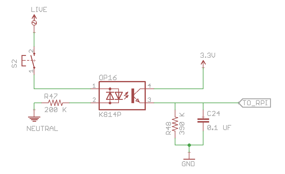
You can use an opto-isolator to convert your 220V to a 3.3V logic system. You can use this circuit for the same:

220V Logic to 3.3V Logic

When you turn on the switch, the optocoupler will get some of the current from it (1-2 mA). This will turn on the transistor and you will detect a HIGH logic with your raspberry pi. Also, your ac input will be sinusoidal so the DC side output will be sinusoidal as well. To take care of this, a capacitor has been used which will ensure a continuous HIGH logic till the ac switch is turned ON.

Once you turn the ac switch OFF, the capacitor will discharge through the 390K resistor and you will get a logic LOW. There will be a delay of approx 100-200 milliseconds though, between switch getting turned OFF and your raspberry Pi detecting LOW because capacitor will take a while to discharge.

Besides being low cost, this circuit also gives you the added benefit of optical isolation. Even if something goes wrong on ac side, your raspberry pi is safe.

\$\endgroup\$
4
  • \$\begingroup\$ How does this compare to using a switching power source as mentioned in the comments of the question? Is it safer? \$\endgroup\$
    – Paul
    Commented Dec 30, 2015 at 16:24
  • \$\begingroup\$ It's cheaper, safer and more compact than using a switching power source. \$\endgroup\$ Commented Dec 30, 2015 at 16:35
  • \$\begingroup\$ Ok, could you please tell me why is there a 200K resistor on the ground wire and why did you choose 390K Ohm and 0.1uF as the values for smoothing the AC current? Thanks! \$\endgroup\$
    – Paul
    Commented Dec 30, 2015 at 16:55
  • 1
    \$\begingroup\$ Left side is basically a resistor connected to two LEDs. You can't connect LED to 220V directly or you will end up destroying it. So you need to add 200K resistor to limit the current. On the right side, I have chosen 0.1uF because it's commonly available as it's used for decoupling. Once the capacitor has been fixed, you need to select a suitable capacitor. If you choose a small value of resistor, you won't get a continuous HIGH when ac is ON. If you choose a large value of resistor, it will take very long to get LOW when ac is turned OFF. \$\endgroup\$ Commented Dec 30, 2015 at 17:00
1
\$\begingroup\$

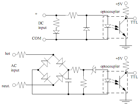
Use an opto coupler like this: -

enter image description here

I've shown two here - the top one works on a dc input and the bottom one has an AC input between live and neutral or, switched-live and neutral. There are simpler versions of this 2nd circuit but this one produces a constant output if AC is present rather than pulsing every time the AC waveform changes (50 or 60 times per second).

You'll need diodes that are reverse voltage rated for the AC supply (1N4007 are usually OK) and the capacitor after the four diodes needs to have a high enough voltage rating (450V).

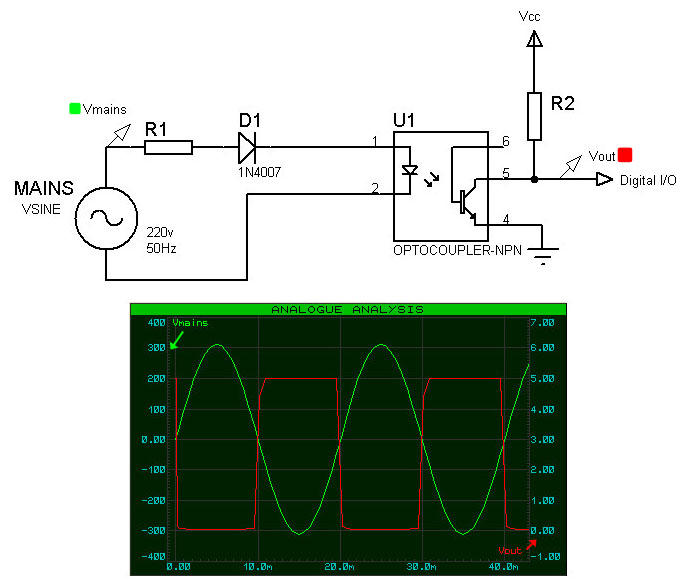
You could use a simpler one like this: -

enter image description here

But, as you can see it produces a switching output. However, if you have this on an IO line you could decide the AC is still powered by waiting for 20 ms to see if it switches.

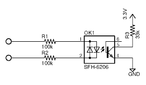
You can even get an opto that switches on both cycles of the AC: -

enter image description here

As before this will produce pulses but a pulse for every half cycle of the AC ~10ms.

\$\endgroup\$

Your Answer

By clicking “Post Your Answer”, you agree to our terms of service and acknowledge you have read our privacy policy.

Not the answer you're looking for? Browse other questions tagged or ask your own question.