1
\$\begingroup\$

I've got an LM358 based ground fault detector circuit that I've recently revised, and the revision broke it, so far as I can tell.

To make a long story short(er), what it amounts to is using one of the LM358 stages as a comparator has whacky output levels. There's a 5 volt supply, and the inverting input has a 20k/100k voltage divider, for a fixed .833 volt comparison level. When the non-inverting input is 0 volts, I would expect the output to be 0. In fact, it's 4.32 volts. If I make the non-inverting input rise up above the threshold, it goes up to around 4.5 volts.

Now, the old version of the circuit had a 1N4148 diode on the output with a pull-down resistor to ground after that.

What is the diode and pull-down supposed to achieve? Why isn't an LM358 acting as I expect without it?

\$\endgroup\$
7
  • \$\begingroup\$ Why not revise with an actual comparator IC? Similar cost, similar pin out. \$\endgroup\$ Commented Dec 31, 2015 at 7:25
  • \$\begingroup\$ LM358 is dual version of LM324 They can do bad things .LM324 is featured in www.badbeetles.com. \$\endgroup\$
    – Autistic
    Commented Dec 31, 2015 at 9:12
  • 1
    \$\begingroup\$ No circuit = no meaningful help. \$\endgroup\$
    – Andy aka
    Commented Dec 31, 2015 at 11:31
  • \$\begingroup\$ @autistic Could you be less specific? \$\endgroup\$
    – nsayer
    Commented Dec 31, 2015 at 16:11
  • \$\begingroup\$ @Andyaka Oh come on. The question is simply to ask the purpose of the diode and pull-down on the output. I can't possibly imagine how adding a schematic would allow that question to be answered any easier. \$\endgroup\$
    – nsayer
    Commented Dec 31, 2015 at 16:13

3 Answers 3

2
\$\begingroup\$

Not every op amp is perfect, nor is an op amp a good substitute for a comparitor. Please consider replacing it with an actual comparitor. As for why you should, that op amp must be pulled down with a 2KOhm resistor or higher in order to meet TTL logic specs (Vcc-1.5 = 3.5V in this case). It's in the datasheet. The Diode is there to prevent the op amp from sinking current and even out the H->L and L->H transition time.

As for why your output is not working. I'd have to see a diagram. From what you describe it should be working.

\$\endgroup\$
6
  • \$\begingroup\$ Hacking a 20k pull-down onto the board fixed it. I didn't see anything like that in the datasheet I have, but there are dozens of manufacturers making it. Can you link to the datasheet where you found that? Could it be caused by the output of the 358 being fed into a high impedance input? So the pulldown is lowering the impedance? \$\endgroup\$
    – nsayer
    Commented Dec 31, 2015 at 18:07
  • 1
    \$\begingroup\$ The LM358 is a TI part. In the data sheet, you'll want to look at output high, or v+ swing, or something like that. In the LM358 data sheet it's called Voh and the test condition is what you have to meet to be in spec. ti.com/lit/ds/symlink/lm358.pdf \$\endgroup\$
    – Dave
    Commented Dec 31, 2015 at 19:03
  • \$\begingroup\$ All I see is the Vol spec, which applies with output impedance of <= 10k. That suggests to me that the maximum output impedance for normal behavior is 10k. Is that why the Vol is more than 3 volts with high impedance? \$\endgroup\$
    – nsayer
    Commented Dec 31, 2015 at 21:08
  • \$\begingroup\$ @nsayer, Voh is literally the box up from that one, on page 8. \$\endgroup\$
    – Dave
    Commented Jan 1, 2016 at 8:52
  • 2
    \$\begingroup\$ Yes, this is one of those reasons you should use a comparitor if you can. That load (2kΩ<Rl<10kΩ) allows the op amp to sink or source enough current to make that voltage. Back to my original answer "Not every op amp is perfect". In this case it won't work as a comparitor in a no load situation. Also, since this has no feedback compensation, try to keep the load from being too capacitive, or you might get ringing. \$\endgroup\$
    – Dave
    Commented Jan 1, 2016 at 20:07
0
\$\begingroup\$

If the output is not connected to something else then there is something wrong with the LM358.

We cannot guess what the function of the diode might have been without a schematic. The LM358 output swings very close to the negative supply if it is only called upon to source current (perhaps 50mV).

\$\endgroup\$
7
  • \$\begingroup\$ The output is connected directly to a microcontroller input pin. There's nothing else. The version of the circuit with the diode and pulldown resistor works. Removing them was the only change made. \$\endgroup\$
    – nsayer
    Commented Dec 31, 2015 at 16:09
  • \$\begingroup\$ Well, my vote is that the micro controller pin is set to output and driving it high. Prove me wrong? \$\endgroup\$ Commented Dec 31, 2015 at 17:12
  • \$\begingroup\$ If it were, then adding the pulldown resistor wouldn't fix the problem. \$\endgroup\$
    – nsayer
    Commented Dec 31, 2015 at 21:26
  • \$\begingroup\$ If the uC port pin is programmed as an output most of the time and momentarily is set to an input, just to read the comparator output, the symptoms would be as you describe. This kind of cleverness is sometimes used to reduce I/O count. A full schematic (and code listing) would make it clear. \$\endgroup\$ Commented Dec 31, 2015 at 23:03
  • \$\begingroup\$ Yeah, that's not what's happening. \$\endgroup\$
    – nsayer
    Commented Jan 1, 2016 at 2:39
0
\$\begingroup\$

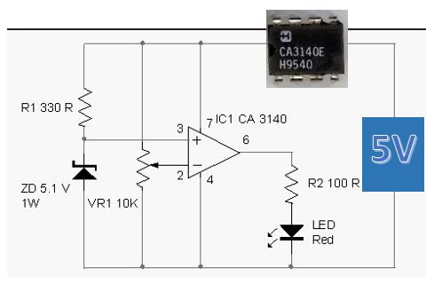
I've been using the CA3140e IC with no probs. You can also buy it with dual op-amp Note: The o/p of the comparator does go to 0v - unlike others! Attached simple example...

enter image description here

\$\endgroup\$

Your Answer

By clicking “Post Your Answer”, you agree to our terms of service and acknowledge you have read our privacy policy.

Not the answer you're looking for? Browse other questions tagged or ask your own question.