4
\$\begingroup\$

I've been studying the schematic for this RLC Bridge from Heathkit (IB-5281). The full pdf can be found here (search for the part number): http://www.vintage-radio.info/heathkit.

The circuit contains an AC source to drive the bridge which is basically a JFET Wien Bridge oscillator with selectable oscillation frequencies. A spice version of the circuit (for 1KHz) is given below: enter image description here
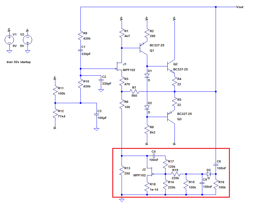
I recognize most of the constituent pieces: the band bass filter, the voltage amplifier and push-pull follower, etc. But I have a few questions:

1) Is the purpose of the feedback through R7 to present a zero phase shifted signal to the source of the jfet to "select" the resonant frequency (similar to how the op amp version works)? How exactly does this mechanism work?

2) What exactly does the section in the red box do? My feeling is it acts like a variable resistor (operating the jfet in its linear region) and pulls more current through the J1 source on positive going half-waves thus providing negative feedback to control the gain, but that's just a guess. I have no clue about D3, C5 and C6.

Thanks.

\$\endgroup\$
2
  • \$\begingroup\$ What a max frequency do you out of this circuit? \$\endgroup\$ Commented Jan 5, 2016 at 21:06
  • \$\begingroup\$ As described in the RLC Bridge manual (see link in question), the oscillator can be selected to run at 100KHz (R=4k3; C=330pF). As to how well formed the sine wave is at this frequency, I have no idea (be aware that I chose different parts for the simulation - according to what I actually have in my kit). I do plan to build and test at some stage, if you get there first let me know how you got on. \$\endgroup\$
    – Buck8pe
    Commented Jan 7, 2016 at 11:05

1 Answer 1

1
\$\begingroup\$

J1 & Q1 provide voltage gain which is buffered by the circuit contianing Q2 & Q3. R7 provides feedback to regulate the voltage gain -- gain is approx (R6+R7)/(R6 + R13+JFET+...).

The circuit in the red box regulates the output amplitude. D3 and C6 (peak) rectify it, and as the amplitude increases, C5 gets charged more and more negative. This pulls the gate of the JFET more negative, and it turns off, thus (because it is in the denominator of the gain equation) decreasing the gain. The gain stabilizes at some (hard to determine) point.

C4 & R17 (especially) provide some specific feedback to make the JFET 'resistor' more linear with drain voltage -- e.g. see this Vishay linearize JFEThttp://www.vishay.com/docs/70598/70598.pdf. This keeps overall distortion low(er).

Not sure what you have for R18 !

\$\endgroup\$
7
  • \$\begingroup\$ Cheers, I'll need to digest all that! R18 was just a dummy resistor to test the source current of J2. \$\endgroup\$
    – Buck8pe
    Commented Jan 1, 2016 at 21:23
  • \$\begingroup\$ How did you work out the gain and in particular why does R7 appear in the numerator? I'm guessing R8/R2 play a part in determining the overall gain (ensuring that Vout > 3)? \$\endgroup\$
    – Buck8pe
    Commented Jan 2, 2016 at 7:18
  • \$\begingroup\$ Also, I can see now that (thanks to the feedback through R7 with Q3 sinking current) you get negative voltage excursions at the top of R13. However, what I notice is that C5 charges less negatively during the positive part of the cycle, which should turn J2 on harder, right? C5 is finally discharged through D3 at the very bottom of the negative cycle (since the voltage at the top of R16 is more negative by the forward voltage of the diode). \$\endgroup\$
    – Buck8pe
    Commented Jan 2, 2016 at 7:26
  • \$\begingroup\$ Apologies, one more question: how is the resonant frequency "chosen"? Is it simply that it has the highest amplitude and other phase offset frequencies fail to make the gain > 1 criteria? \$\endgroup\$
    – Buck8pe
    Commented Jan 2, 2016 at 7:33
  • \$\begingroup\$ Gain: Think of J1 as an emitter follower, and ignore R3. The feedback will drive the junction of R7 & R6 to be about the threshold V of J1 away from the input voltage (at its gate). So VOUT*R6/(R7+R6) = VIN. Note this is AC gain -- there are some DC offsets (VTH of J1 for instance, bias current in R3 etc.) also. C5 charges to the negative peaks of each cycle (-diode drop). It is the magnitude of this negative peak that is regulated. Resonant frequency is where the phase shift through the bridge (R9, C1, R10, C2) is 0 deg (+/- some small 'errors' in phase through the buffer). \$\endgroup\$
    – jp314
    Commented Jan 2, 2016 at 15:50

Your Answer

By clicking “Post Your Answer”, you agree to our terms of service and acknowledge you have read our privacy policy.

Not the answer you're looking for? Browse other questions tagged or ask your own question.