1
\$\begingroup\$

Posting my question with a schematic

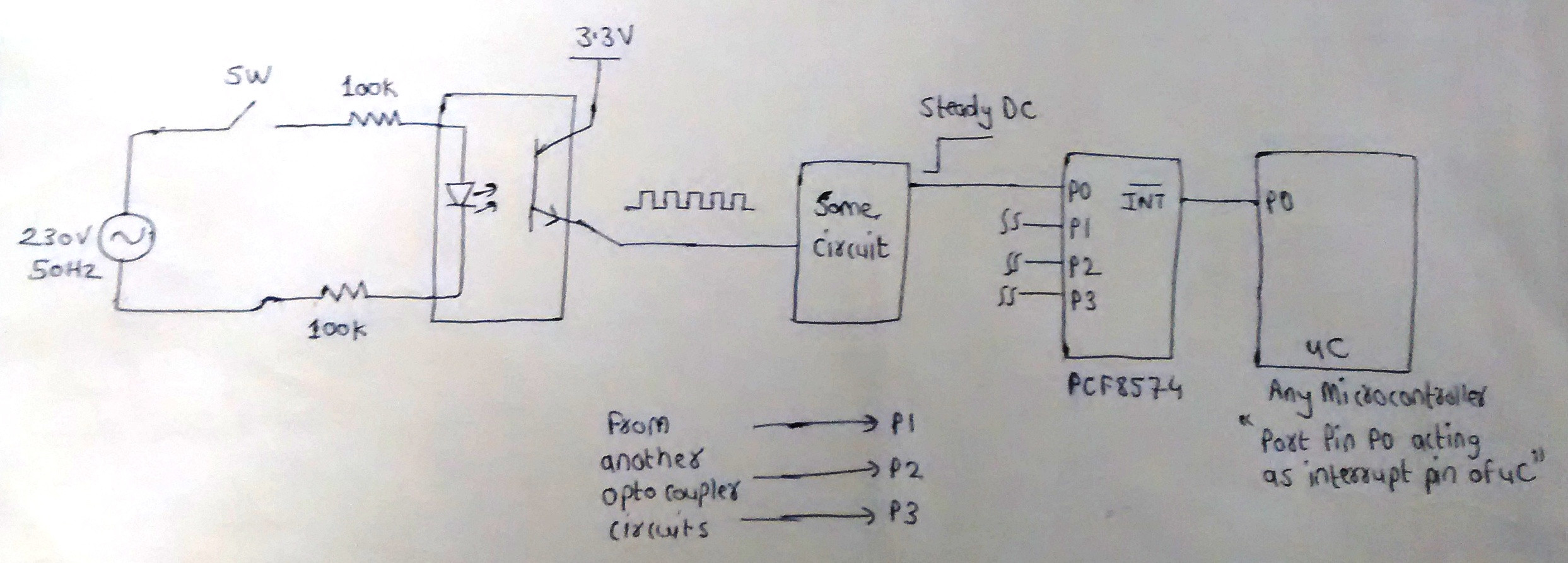
I want to detect AC line voltage using an optocoupler. When i feed the optocoupler input with an AC line, i get a 50 Hz pulse train at the output. Usually this scheme is used for a zero cross detection. But my idea is to use this pulses and convert them to a steady DC pulse so that i can feed this pulse at the input of a PCF8574. In that way i would know the status of PCF8574 port pins and hence the presence of an AC voltage as shown in the schematic below

enter image description here

When i close switch SW, a pulse train is generated at output of opto-coupler. I want the "some circuit" block to generate a steady pulse from the opto-coupler output. When the switch SW is open, there is absence of pulse train and want the "some circuit' block to output a zero until the switch SW is turned ON again.

Now my question is:

How can i convert a pulse train to a steady DC? I want the "some circuit" block in above schematic to do the job, so what circuit can replace the "some circuit" block

Also, is it the correct way to interface an opto-coupler with "some circuit" block ? I am getting a pulse train at emitter of the optotransistor Please correct me if i am wrong

Please share any circuits or ideas

Thanking you,

Gaurav


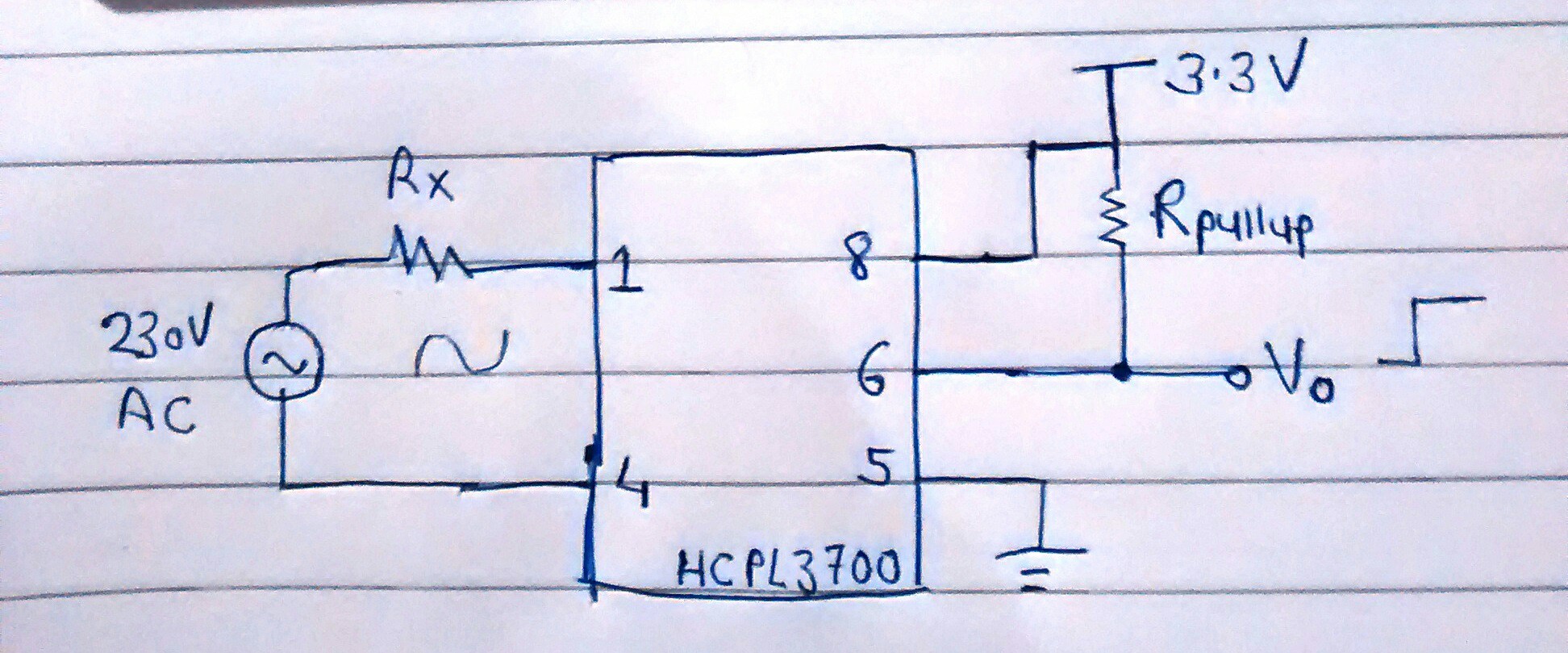
Basically i want to know whether 230V AC Mains is present or not, so if i use HCPL3700 opto-coupler as shown below, will it do the job for me?

I just want a single steady pulse, so i assume if the AC signal crosses a certain threshold, the HCPL3700 will output a HIGH and when AC signal is absent it will output a LOW.

Am i right ? Please suggest
AC mains detect

\$\endgroup\$
6
  • \$\begingroup\$ Can you not do this in software? Periodically check for high on the input and if you don't see it for a few cycles then assume power is off. \$\endgroup\$
    – Transistor
    Commented Jan 2, 2016 at 12:34
  • \$\begingroup\$ @transistor: I am using PCF8574 interrupt pin to signal my microcontroller whether there is any state change on any of its port pins. For the code to work properly i need a single interrupt pulse which will never repeat unless there is a change on any of the port pin. But, as i am getting a pulse train from the output of optocoupler, the PCF8574 port pins are being pulsed at 50 Hz. As a result the interrupt signal from PCF8574 too is pulsing at the same rate. So my microcontroller gets the interrupt signal every time which is not desired \$\endgroup\$ Commented Jan 2, 2016 at 15:25
  • \$\begingroup\$ Your sketch doesn't show any reverse polarity protection on the optocoupler LED. It must be built in or it would be smoked by now. \$\endgroup\$
    – Transistor
    Commented Jan 4, 2016 at 1:16
  • \$\begingroup\$ If you original question is to detect that AC line has some voltage present, I would suggest converting it to DC and put a low-level triggered interrupt. So, whenever the AC line goes poof; automatically DC will shift to zero and ISR will be called. \$\endgroup\$
    – ammar.cma
    Commented Jan 5, 2016 at 12:48
  • \$\begingroup\$ @ammar.cma : That was the basic idea at first, but converting 230V AC to its peak value DC, is it safe? My pcb will be having everything on-board so i feel its not safe to handle such high DC voltage before opto-coupler. If i try to step-down the AC voltage and convert it to DC, the opto transistor does not switch ON full. \$\endgroup\$ Commented Jan 5, 2016 at 13:04

6 Answers 6

0
\$\begingroup\$

Using a retriggerable one shot like the 74ls123 with an on time longer than one full AC cycle will be enough to make your circuit work.These "digital monostables" are not stunningly accurate because the time constant relies on logic gate thresholds and analog components .This means that your proposed production circuit should have a RC constant of say 40ms .

\$\endgroup\$
2
  • \$\begingroup\$ thank you, I will try simulating with 74Ls123 IC, decide the RC constant and let you know if that works \$\endgroup\$ Commented Jan 5, 2016 at 13:29
  • \$\begingroup\$ It worked using 74LS123. Purposely kept RC time constant about 90 ms to remain safest \$\endgroup\$ Commented Jan 16, 2016 at 5:49
1
\$\begingroup\$

The filter will give you a signal: AC present/AC not present, but I would let the software check the status unless your INT would interupt the controller in all cases. If you are unlucky, the controller might miss a flank and be in a wrong state.

\$\endgroup\$
1
  • \$\begingroup\$ Suppose the actual port status of PCF8574 is 251. Now when any of my PCF8574 port pin state changes then lets say the new state is 253. The PCF8574 pin goes low whenever a state change is occurred on any of the PCF8574 port pins. If i input a pulse train say at 100 Hz at any port input, the INT pin too will get pulsed at same rate. This will interrupt the microcontroller every time and it reads value as 251, 253, 251, 253.... This is undesired. So i want a steady pulse at the input of PCF8574 so that the INT pin goes low only once and micro would read the new status \$\endgroup\$ Commented Jan 4, 2016 at 5:25
0
\$\begingroup\$

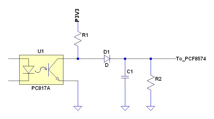
One way to do this is to place a filtering circuit between the output of the opto-coupler and the input of the PCF8574.

A circuit that could so this for you would look like this:

enter image description here

Whenever the 50Hz signal is present the high times of the signal will allow R1 to charge capacitor C1 through D1. Select values so that after a pulse or two of the 50Hz the C1 is charged to a high level to be seen at the PCF8574.

Resistor R2 is in place so that the capacitor will discharge back to a low level when the 50Hz pulses stop coming.

Last thing to consider is that depending on the input signal characteristics of the PCF8574 you may want to buffer the signal from the circuit below through a Schmidt trigger type gate to square up its rise/fall times.

\$\endgroup\$
11
  • \$\begingroup\$ Thank you for the reply, I will try implementing the circuit you suggested on a breadboard and leave a feedback very soon \$\endgroup\$ Commented Jan 2, 2016 at 8:13
  • \$\begingroup\$ Note of caution. If you select the resistors R1 and R2 it will be desired that R2 >> R1 so that the voltage divider effect of the two does not limit the high level voltage achievable on C1. If that voltage ends up too low the target device will not be able to recognize it as a high level. \$\endgroup\$ Commented Jan 2, 2016 at 8:18
  • \$\begingroup\$ The high threshold voltage level for PCF8574 is 0.7Vcc which for a 3.3 V is around 2.31 Volts. And a low threshold level is 0.3Vcc which is about 0.99 Volts. So i will choose R1, R2 and C appropriately to meet the IO specs of PCF8574. I will simulate the circuit first before breadboarding it and get back soon \$\endgroup\$ Commented Jan 2, 2016 at 8:37
  • \$\begingroup\$ Could also put a bridge and cap before the opto-isolator. \$\endgroup\$
    – user57037
    Commented Jan 2, 2016 at 8:45
  • \$\begingroup\$ that circuit will not work: when the AC is not present, what happens? \$\endgroup\$ Commented Jan 2, 2016 at 11:39
0
\$\begingroup\$

It is impossible to convert a pulse train into a single DC pulse as shown in your diagram becuase it would require that your circuit be able to see into the future and detect events that have not yet occured.

Imagine that it is currently at the moment of the falling edge of the 3rd and final input pulse. In order to know that it is time to lower the output single, you would need to know that there was not another input pulse coming.

The best you can hope for is to do something like "output a single pulse that rises when the input rises and falls after the input has been low for at least n amount of time".

Note that the n can be dependant on timings of the input pulse, but only things that could be measured up until that moment in time.

\$\endgroup\$
0
\$\begingroup\$

Neon-LDR optocoupler

I offer this as an incomplete answer as I have not tested it.

schematic

simulate this circuit – Schematic created using CircuitLab

All of the LED optocouplers suffer from high dissipation in the mains voltage dropping resistors and generate some heat on the board. The LED current varies during the mains cycle and so trade-offs have to be made. It is possible to drop voltage using a capacitor but additional components are required to handle transients on power-up.

Neons are relatively low-power and a 1/4 W 220 kΩ resistor is all that's required to light it from 230 V mains. An LDR (light dependent resistor) is used on the low-voltage side. In the schematic above I have added a 1 uF capacitor to maintain the 'mains present' signal during the zero-cross.

Neon optocouplers were used by Fender guitar amplifier vibrato circuits and are still available. A web search for 'neon optocoupler' shows up some more recent implementations for modern micros for 'mains presence' rather than the usual zero-cross applications.

Fender neon optocoupler - http://shop.sonnywalton.com

Neon optocoupler for Fender vibrato. Note use of opaque heatshrink to prevent ingress of stray light. The neon appears to be on the left with bulb point visible pointing to the LDR on right.

Given that four circuits are required in the question, I suggest that this idea is worth consideration. The neon optocoupler can be home-made using a regular neon, an LDR and black heatshrink.

\$\endgroup\$
3
  • \$\begingroup\$ Thanks for pointing out the reverse polarity issue. I will add a diode in anti-parallel at the input of my opto-coupler. This will give a 100 Hz pulse train at the output which is no any issue to me. The neon-LDR optocoupler suggested seems to be a good replacement to existing PC817, but unfortunately that type of opto-coupler is not readily available in the local market near my place. \$\endgroup\$ Commented Jan 4, 2016 at 5:12
  • \$\begingroup\$ You could make them using a neon, LDR and heatshrink. \$\endgroup\$
    – Transistor
    Commented Jan 4, 2016 at 7:18
  • \$\begingroup\$ I will try building one, but at the moment i am stucked at the original problem of converting pulse train to a single pulse since 2 weeks \$\endgroup\$ Commented Jan 4, 2016 at 7:22
0
\$\begingroup\$

I wanted just the same solution when working with an LED indicator running at 50-Hz mains frequency and convert that to steady single pulse while the LED was "on". The retriggerable 74HC123 works really well as mentioned before (using 20-mS retrigger to keep it sharp), but eventually used software on Arduino, quite simple, where the incoming pulse (from a TSL257 optical sensor) kept resetting the 20-mS timer - when no pulse was received, the timer (actually a mS counter) timed out and alarmed or whatever. It's a really useful way to monitor mains. The beauty of the software approach is that you can make the retrigger time as long as you like. I also use the HCPL3700 instead of relays to monitor pumps running etc.

\$\endgroup\$

Your Answer

By clicking “Post Your Answer”, you agree to our terms of service and acknowledge you have read our privacy policy.

Not the answer you're looking for? Browse other questions tagged or ask your own question.