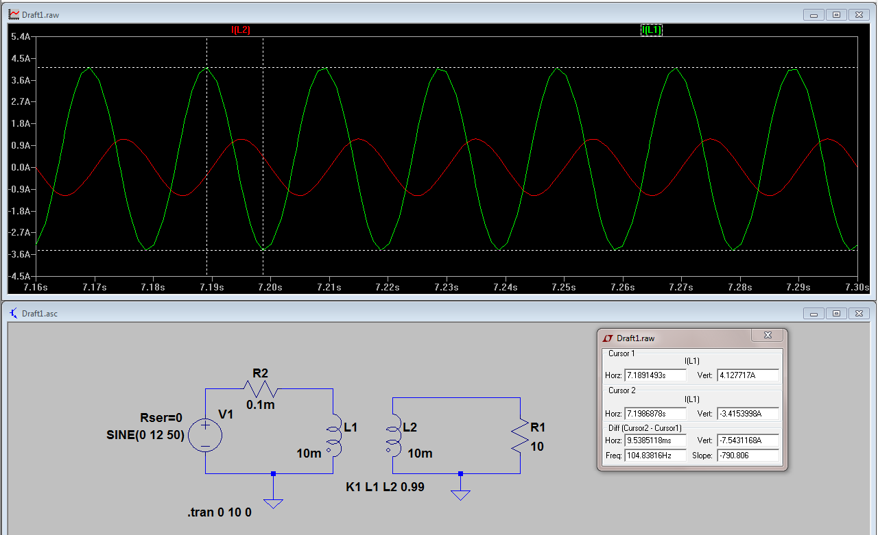
I am trying to simulate a transformer with a turn ratio of 1:1. The voltage of the primary and secondary are equal but I am getting a different current in the winding (why?). Also I see some DC offset in the primary current (why?). Please correct me if I am simulating design wrong. Thanks
2 Answers
I am getting different current in winding(why?)
The primary current contains the load current AND the magnetization current. The secondary current is only the load current.
Magnetization current is due to the voltage supply being attached to an inductor (with secondary open circuit).
You'll need to be clearer about what DC offset you are seeing but i suspect it doesn't really exist after the first few cycles of AC have passed.
-
\$\begingroup\$ sorry I am not able to comprehend the explanation.If it is not a problem can you explain with equivalent circuit of transformer \$\endgroup\$– jokeroorCommented Jan 11, 2016 at 10:25
-
\$\begingroup\$ What is it you are unable to comprehend and how well do you read English? The words I have used are fairly simple I believed but I'm not about to guess what you don't understand so please be explicit. \$\endgroup\$– Andy akaCommented Jan 11, 2016 at 10:26
-
\$\begingroup\$ My English is fine.Is there a way we can see both component of Primary current i.e. load and magnetising current? \$\endgroup\$– jokeroorCommented Jan 11, 2016 at 10:49
-
1\$\begingroup\$ Or, I(L1) has the current flowing into a 10mH inductor plus the current flowing into a 10 ohm load. So that's a peak of 3.8197A into the 10mH and a peak of about 1.188A flowing into the load. Added together as per \$\sqrt{A^2+B^2}\$ and you get 4 A peak in primary \$\endgroup\$– Andy akaCommented Jan 11, 2016 at 11:52
-
1\$\begingroup\$ To see the magnetising current alone, disconnect the load. \$\endgroup\$– user16324Commented Jan 11, 2016 at 14:10
As @Andyaka said, the primary current is the sum of the load current and the magnetizing current. The secondary current is just the load current.
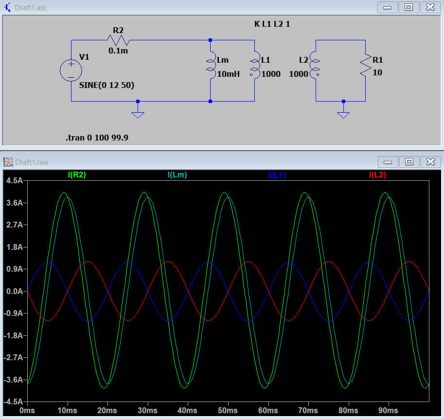
If you want to see them separately you can use the equivalent circuit of the transformer. To make an ideal transformer you set the inductance to be high enough (ideally infinite). Then you add a magnetizing inductance in parallel with the primary equal to your transformer inductance (10mH in your case).
As you can see I(L1) and I(L2) now match perfectly. I(Lm) is the magnetizing current. I(R2) is the primary current that you were seeing in your simulation and is the sum of I(L1) and I(Lm).


