2
\$\begingroup\$

I work at a manufacturing plant (in software engineering) and we have 3rd party hardware and software that monitors industrial machinery (primarily speeds).

For training and testing we need to be able to emulate one of the machines. The 3rd party hardware is based on the Omron CP1L-EM30DT1-D PLC - (http://datasheet.octopart.com/CP1L-EM30DT1-D-Omron-datasheet-12510914.pdf)

I was going to build something simple using a variable speed DC motor and encoder wheel to generate pulses, but then it dawned on me, can't I just use an arduino and software to send variable frequency pulses? It doesn't need to be very accurate. We'd probably want a range of 1,000 to 60,000 per hour.

I'll admit that I know nothing about PLC's (yet), so I'm looking for guidance.

What would I need to send pulses to this PLC from the arduino (I'm assuming I need 24v DC so would have to switch that via a relay)? I'm trying to get some information from our vendor too. They said I could do something simple with a push button (but I'm trying to get more info). Not sure if this would help determine what I need to do.

Initially, I'll use constants in the sketch to set the speed on startup, but long term, I'd add some kind of speed control using a rotary switch or pot and hard buttons for stop and start.

Thanks in advance

Mark

\$\endgroup\$

3 Answers 3

3
\$\begingroup\$

schematic

simulate this circuit – Schematic created using CircuitLab

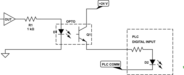
Figure 1. Opto isolator interface to PLC. The PLC digital input can take 24 V DC.

An opto isolator has the advantage of galvanic isolation, high speed, low cost and no moving parts.

\$\endgroup\$
3
  • \$\begingroup\$ This looks good (and easy :-) ). the OUT is the arduino digital output, right? Any suggestions on a part no for the opto? DO I need any resistors between 24v and opto, or opto and plc input to limi the current? \$\endgroup\$
    – mark1234
    Commented Jan 14, 2016 at 19:05
  • \$\begingroup\$ Nearly any transistor opto will do. D2 is simplified representation of PLC input. It has internal resistance and will take full 24 V and draw 10 mA or so. \$\endgroup\$
    – Transistor
    Commented Jan 14, 2016 at 19:43
  • \$\begingroup\$ Updated schematic to show internal resistance for 24 V input. \$\endgroup\$
    – Transistor
    Commented Jan 14, 2016 at 20:33
3
\$\begingroup\$

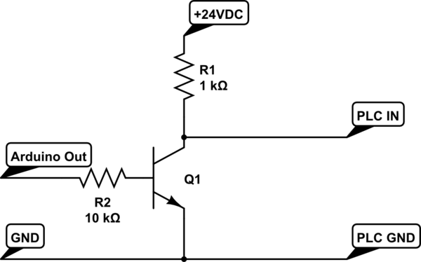
This is easiest:

schematic

simulate this circuit – Schematic created using CircuitLab

Output high from the Arduino sends a low to the PLC.

Output low from the Arduino send a high to the PLC.

Any small signal NPN transistor than can handle more than 24 volts should work.


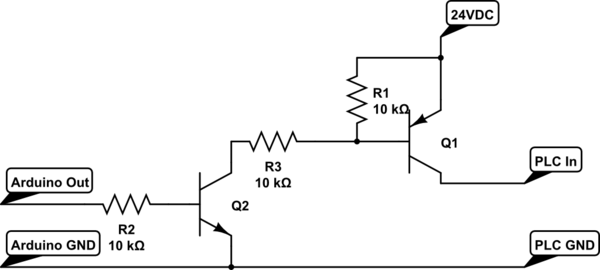
This is almost as easy:

schematic

simulate this circuit

You don't have to invert the Arduino output for this, and it doesn't waste current through the pullup like the first circuit did.


Note that the PLC has opto isolated inputs, so it is well protected. Using another opto isolator from the Arduino would protect it from anything that might happen on the 24Volt and ground lines to the PLC.

The opto isolator in the PLC also has a series resistor, so you shouldn't need a resistor in the line going to the PLC input - doing so would probably cause trouble (not switching or slow switching.)

\$\endgroup\$
7
  • \$\begingroup\$ Shouldn't there be an extra R to limit the current in Q1-Q2 circuit? Or is carefully choosing the value of R2 enough? \$\endgroup\$ Commented Jan 14, 2016 at 15:31
  • 1
    \$\begingroup\$ @DmitryGrigoryev: Thanks. I left a resistor out of the diagram. The way I had it would probably have burned out both transistors. \$\endgroup\$
    – JRE
    Commented Jan 14, 2016 at 15:35
  • \$\begingroup\$ @JRE deos the post have all the resistors in? any suggestions on part no's for Q1 and Q2? \$\endgroup\$
    – mark1234
    Commented Jan 14, 2016 at 19:07
  • \$\begingroup\$ I updated the schematic, so it has all the resistors now. \$\endgroup\$
    – JRE
    Commented Jan 14, 2016 at 19:20
  • \$\begingroup\$ NPN: 2N2222 or BC548 or 2N3904 \$\endgroup\$
    – JRE
    Commented Jan 14, 2016 at 19:20
0
\$\begingroup\$

PLC simulator code option

It is common practice in the PLC world to build simulation into the device being controlled. It is most likely that there is plenty of program memory left and that a simulator can be added to generate an internal pulse train and, if you really want, make it available on a digital output to feed back in on the counter input.

There are two analog inputs built into those PLCs, as far as I can make out, and some seem to even have a built-in potentiometer. If yours doesn't have a pot you can wire one up as shown below.

schematic

simulate this circuit – Schematic created using CircuitLab

Figure 1. 0 - 10 V analog control.

My approach would be:

  • Wire up the analog input.
  • Write code to generate a pulse train at a frequency set by the potentiometer. Internal value will be 1,000 counts at 10 V on analog input.
  • Modify program to add 'simulator' bit set by programming software, HMI or wired input.
  • Modify the code to use the simulator if the bit is set and to use the real input otherwise.
\$\endgroup\$
1
  • \$\begingroup\$ thanks for suggestion, but we do want a true simulation of what a physical machine would do (for testing purposes). Seems like a much longer learning curve. We're in a bit of a crunch and I already know arduino. thanks again for taking the time \$\endgroup\$
    – mark1234
    Commented Jan 14, 2016 at 19:04

Your Answer

By clicking “Post Your Answer”, you agree to our terms of service and acknowledge you have read our privacy policy.

Not the answer you're looking for? Browse other questions tagged or ask your own question.