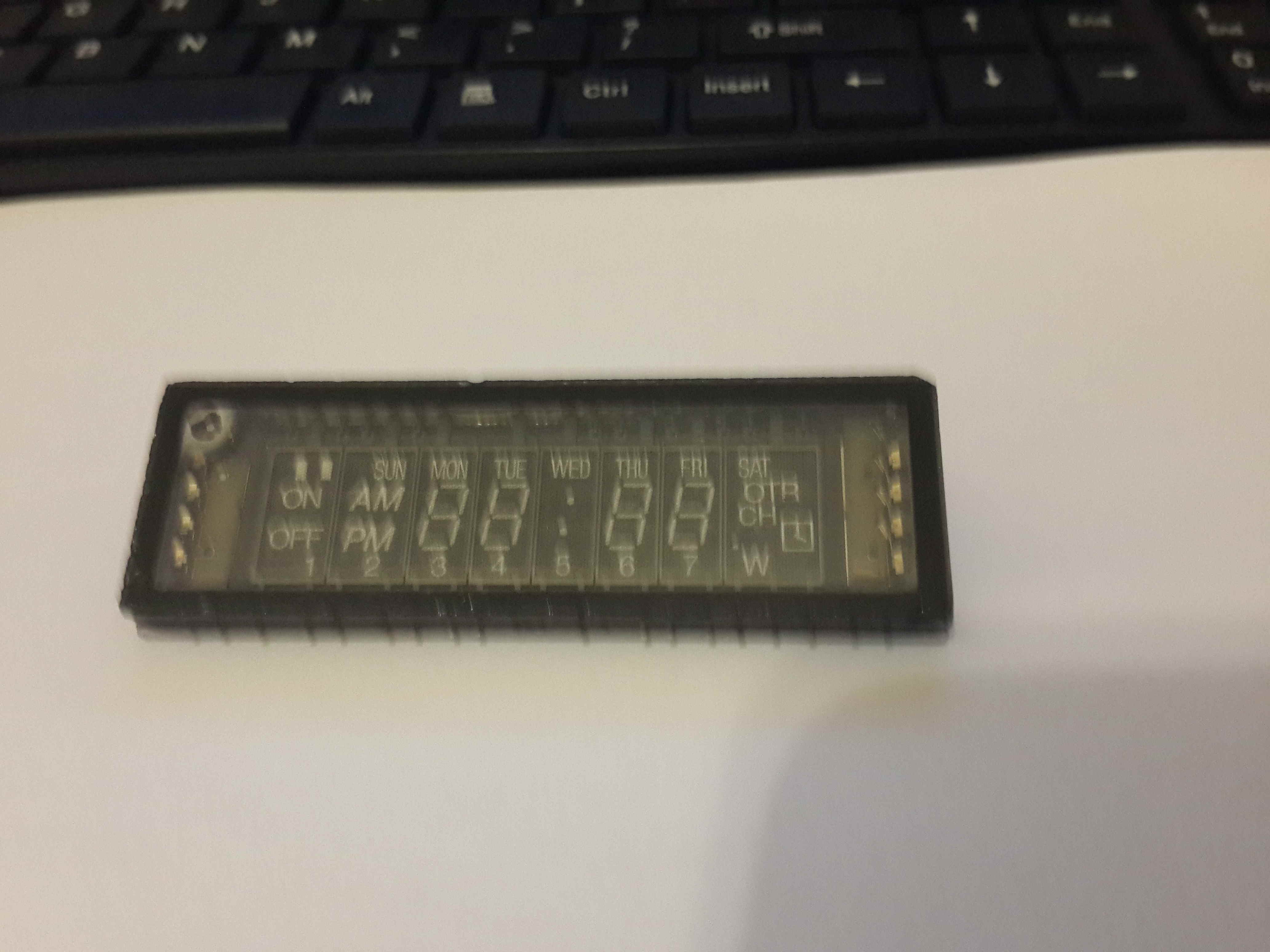
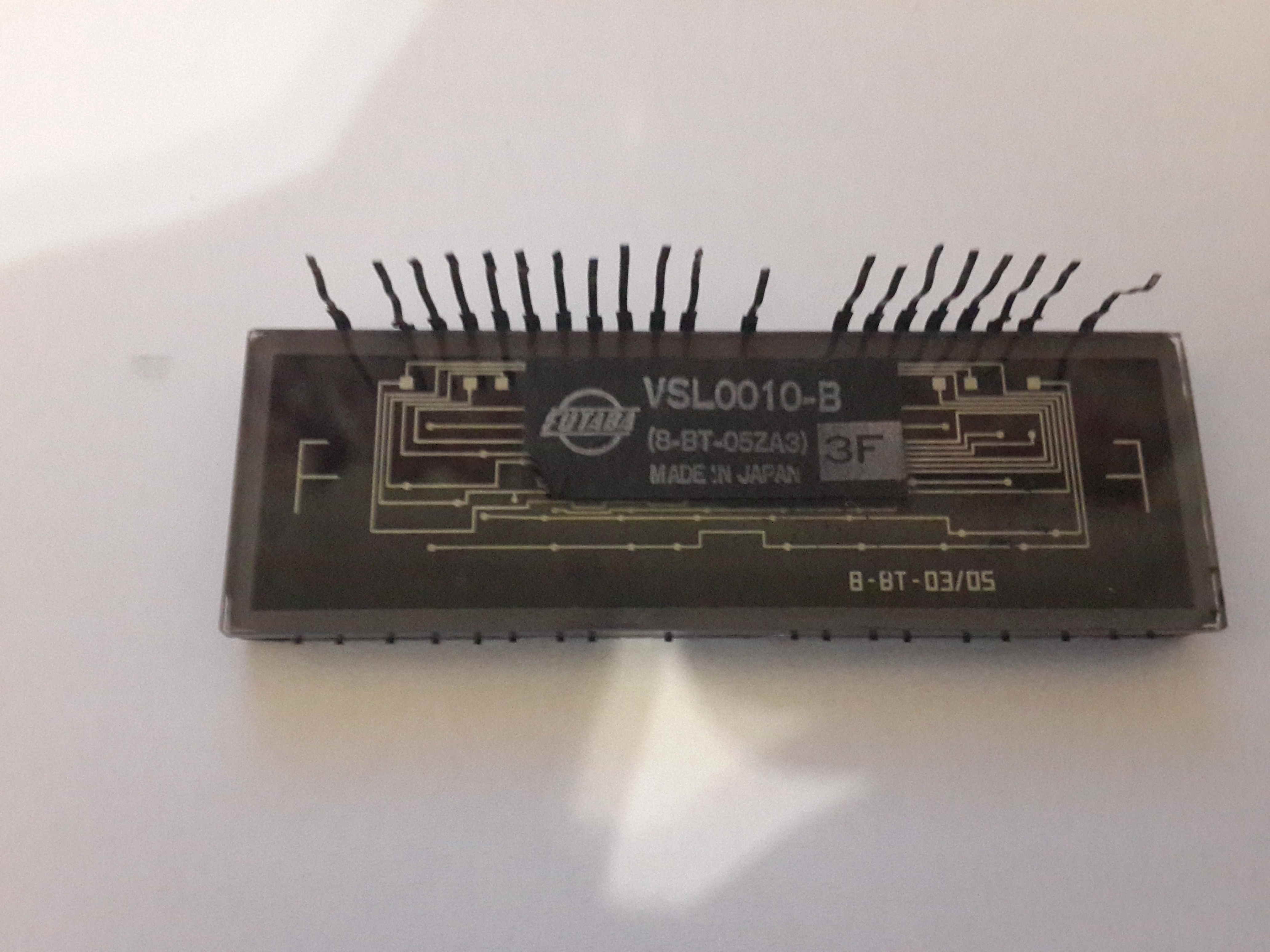
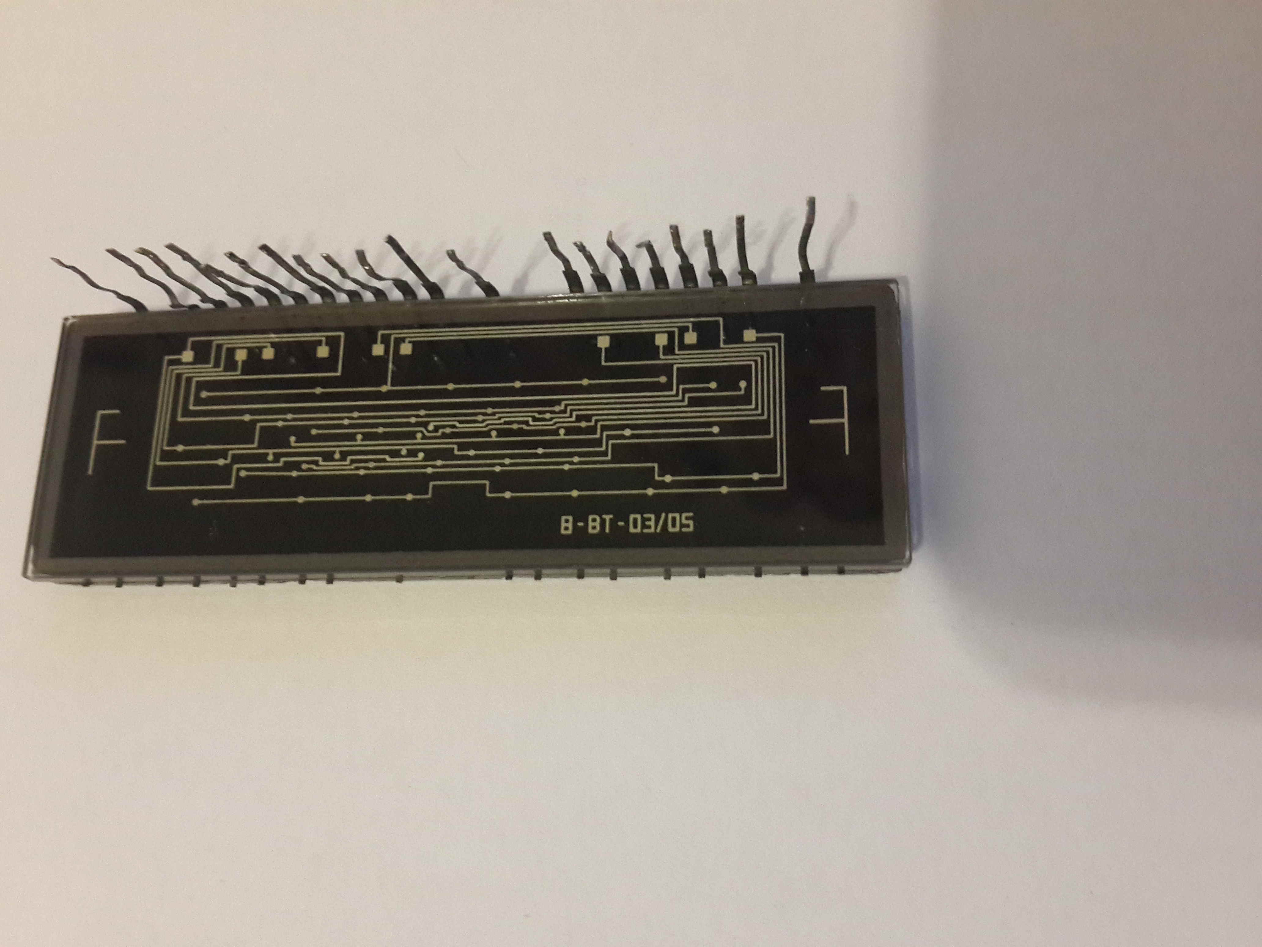
I salvaged this display unit from an old VCR about 20 years ago. Since then, it's been lying in my electronics box. Now I would like to play around with it on an Arduino. I can't find the datasheet for this VFD online. I've never used a VFD before, so this is completely new ground for me. Any assistance would be greatly appreciated.
-
1\$\begingroup\$ Forget it (perhaps for another 20 years). Don't waste time with this. Get a display that comes with a datasheet. (By the way, here's a discussion about cons and pros of salvaging components this day and age.) \$\endgroup\$– Nick AlexeevCommented Jan 17, 2016 at 21:11
-
1\$\begingroup\$ Looks like a raw display, no power or data controller. Good luck \$\endgroup\$– PasserbyCommented Jan 17, 2016 at 21:59
-
\$\begingroup\$ @Nick, it's not about having a display, it's about playing with this display and learning how it works. But, based on what I've been reading, it does seem you have a point. Thanks for an honest opinion. \$\endgroup\$– Richard CCommented Jan 17, 2016 at 22:15
-
\$\begingroup\$ @Passerby, it seems that you are correct. That leaves me even more lost as to a starting point. \$\endgroup\$– Richard CCommented Jan 17, 2016 at 22:16
1 Answer
These VFD displays are not so easy to drive unfortunately ! They require a high voltage, in the order of 50 V DC for the anode and a lower voltage but with some current capability to power the filament (those are the very thin wires at the fron of the display just under the front glass). To light up an element it has to be pulled down to ground as far as I know.
Have a look at this page where the author shows how to build a clock using some small VFD tube displays. Althoug their shape is different, the technology inside is the same.
-
\$\begingroup\$ Wow. High voltage. I'm even more intrigued now. But I don't have the equipment to drive that at the moment. Maybe in another 20 years :). I looked at your link. Those tubes have a pin per display segment, plus the anode and cathode . Mine has many fewer pins than that. Thanks for an informative answer. \$\endgroup\$ Commented Jan 17, 2016 at 22:13
-
\$\begingroup\$ Your display is divided in 8 groups of elements, each group has a connection pin (so 8 pins). Each group contains a few elements, the elements share share the pins so for example the 1, 2, 3 ..7 at the bottom of each group share one pin. But these elements will only light up if that common pin has the right voltage AND the group pin has the right voltage. It's like a matrix. It saves A LOT of pins :-) \$\endgroup\$ Commented Jan 18, 2016 at 8:12
-
\$\begingroup\$ @RichieACC it may work, barely visible, even from 12v. Try, it may work. \$\endgroup\$– ilkhdCommented Jan 18, 2016 at 10:11


