0
\$\begingroup\$

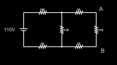
I'm trying to find E Thevenin between points A and B. I found the Thevenin resistance, but I'm having trouble finding the voltage.

Note that there were wires that connected the load resistor, but since it's removed, I moved the nodes all the way to the 110 resistor.

I started out like this: since 165 and 55 are in series, their equivalent resistance is 220 ohms. Therefore, the current in this branch is I = 110V / 220Ω = 0.5A. Is that correct? Obviously the voltage U(AB) is the same as the voltage across the 110 resistor. The 110 resistor is a voltage divider, am I right? So how do I apply the voltage divider formula to find the voltage across the 110 resistor (the one in the middle)?

enter image description here

\$\endgroup\$
3
  • \$\begingroup\$ Try this: combine the 165R and 55R below it. Then do a source transformation. Then you can combine the left 110R, and do another source transformation. I'll leave the rest to you. \$\endgroup\$
    – uint128_t
    Commented Jan 20, 2016 at 16:41
  • \$\begingroup\$ I end up with a current source of 0.5 A on the left, and a 55 ohm resistor on the right. That gives me a voltage of 27.5V, which isn't correct according to my simulator... Maybe the 165 and 55 are combined parallel? (I combined them like they were in series) \$\endgroup\$
    – Quant
    Commented Jan 20, 2016 at 16:54
  • \$\begingroup\$ You'll have to post your work, something's going wrong somewhere. Remember to keep doing source transformations and combining resistors until you have only a Thevenin source. Incidentally, what does your simulator say? \$\endgroup\$
    – uint128_t
    Commented Jan 20, 2016 at 17:05

3 Answers 3

1
\$\begingroup\$

One way is to do the thevenin twice.

  1. the circuit with 110V source, 165R, 110R and 55R. Output R = 220 in parallel with 110 = 73.33R Offload V = 36.67V

  2. Add the remaining circuit. We have 36.67V source in series with 73.33 + 55 + 55 = 183.33ohms. This is potted down by the 110R Output R is 183.33 in parallel with 110 = 68.75R Vout offload = 36.67 / (183.33 + 110) * 110 = 13.75V

Answer: Equivalent = 13.75V + 68.75ohms

\$\endgroup\$
1
\$\begingroup\$

I agree with step 1 from @user1582568

However, the equivalent is 36.667 with a series R of 183. So, all the Rs are in series for step 2 (36.667 is applied across 183.333 + 110 = 293.333 ohms). Thus the current is simply 36.667 / 293.3333 = 0.125 A.

0.125 A times 110 ohms = 13.75 V.

Does that agree with your simulation?

\$\endgroup\$
4
  • \$\begingroup\$ Yes it does, thank you! But one question, to see if I got it right: at the end we have a 36.67V voltage source in series with 73.33 + 55 + 55 + 110? How did we get this new voltage? \$\endgroup\$
    – Quant
    Commented Jan 20, 2016 at 17:24
  • \$\begingroup\$ @MikeP I think you got the same answer as me, did you think my answer was incorrect? \$\endgroup\$ Commented Jan 20, 2016 at 17:36
  • \$\begingroup\$ @Quant the voltage is obtained as in my answer. We pot down 36.67V by a resistances 183.33oms and 110ohms, so the current in the divider would be 36.67 / (183.33 + 110). then multiply this by 110 to get 13.75V. \$\endgroup\$ Commented Jan 20, 2016 at 17:40
  • \$\begingroup\$ @user1582568, sorry I must have misunderstood. I divided 68.75 by 13.75 and got 0.200 A, so I thought something wasn't exactly right. \$\endgroup\$
    – MikeP
    Commented Jan 20, 2016 at 18:04
0
\$\begingroup\$

As you already know, computing a Thevenin Equivalent involves 2 parts:

  1. Computing \$Z_{TH}\$
  2. Computing \$V_{TH}\$

Obtaining \$Z_{TH}\$

As you have already computed it I am going to discuss briefly how I would get it to see if we agree.

After shorting out the voltage source we find that: $$Z_{TH} = (165 + 55)//110 + 55 + 55 = \frac{(165 + 55)·110}{165 + 55 + 110} + 55 + 55 [Ω]$$

Where (//) denotes the parallel of those resistors and (+) the series equivalent. Note how the // operation takes precedence. Carrying it out shows \$Z_{TH} = 183,83 Ω\$

Obtaining \$V_{TH}\$

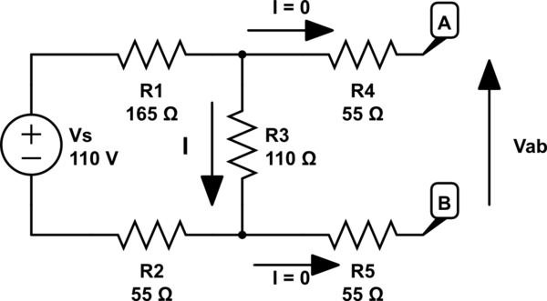
As you pointed out, having an open circuit between terminals A and B "removes" all the resistors in the right mesh from the circuit (namely both 55 and the right-most 110 ohm resistors). We also see how \$V_{AB} = V_{TH}\$ is indeed the same as \$V_{R=110}\$. The only thing we have to do is obtaining that \$V_{R=110}\$. To do so we will solve the left-most mesh. Obtaining the current follows Ohm's law and it is given by: $$I =\frac{V_{Source}}{R_{165} + R_{110} + R_{55}} = \frac{110V}{165Ω + 110Ω + 55Ω} = 0,33A = 333,33mA$$

Then: $$V_A = V_B + I·R_{110} \to V_A - V_B = V_{TH} = I·R_{110} = 0,33A·110Ω = 36,67V$$

If you want to see the "equation" for the voltage divider you can just substitute I in the second equation for the expression we obtained in the first one and you would get: $$V_{TH} = \frac{V_{Source}}{R_{165} + R_{110} + R_{55}}·R_{110}$$

Finally, here is the circuit with the current I used:
schematic

simulate this circuit – Schematic created using CircuitLab

\$\endgroup\$

Your Answer

By clicking “Post Your Answer”, you agree to our terms of service and acknowledge you have read our privacy policy.

Not the answer you're looking for? Browse other questions tagged or ask your own question.