-1
\$\begingroup\$

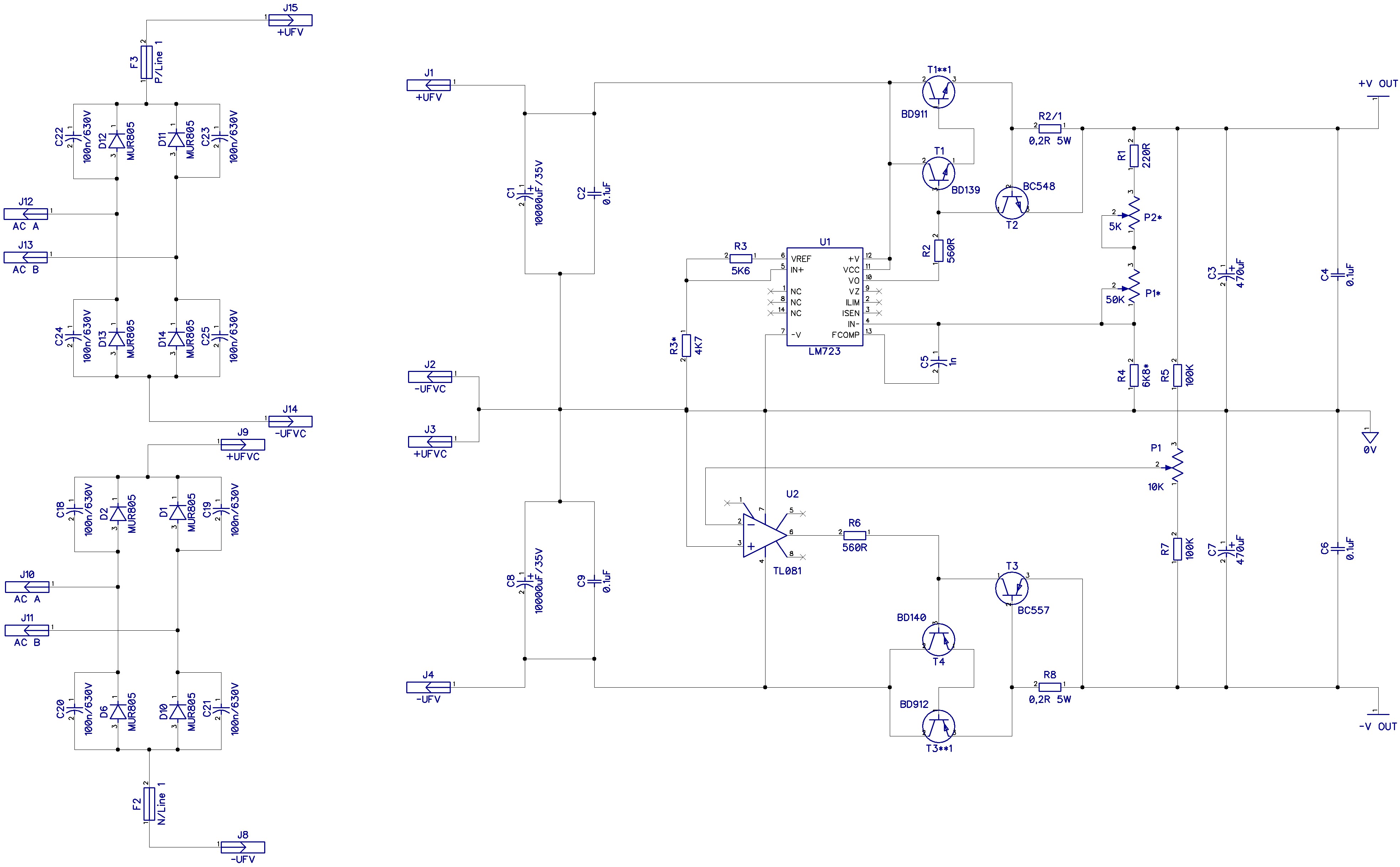
So I decided to build power supply unit for my modular synthesizers. 2-in-1 Design: +/-15V (3A each) and +5 (1A) for TTL logic ICs modules. I started from enclosure, learning the SolidWorks in the same time. So after the box was finished I started to look the easiest and rugged solution for 7A PSU. Sure it is linear design I had to choose from. So for the TTL Ics, where 1A is enough I chose classic 7805 regulator with crowbar over-voltage protection. And for the +/-15 3A rails LM723 with current booster. Later I decided to add EMI-filter and soft start (tactile button and surge protection in one circuit). Soft start will use 7812 regulator and two 24V relays powered from 250mA stand-alone power transformer. This work took 3 month, and before go to production stage I wanted to check everything once again and ask an advice on this particular implementation. First requirement is protection, and safety, coz this PSU will supply 12k setup of modules. The second one is not to be overkilled. Also I'm interested in ways to reduce impedance if there is a common practice to do it, avoiding the complex procedures of measurement the unit under load. And it could be possible that I have made a mistakes, as fatal and minor ( I suspect that could make mistakes in the diode bridges) so kindly ask you to help me eliminate them. And the last thing is transformer, still can not calculate required VA and voltage of secondary.

So here is my +5V circuit enter image description here

And +/-15V based on LM723 enter image description here Here are specific questions about this: 1. What is the best caps to use for c4 and c6 at the voltage outputs? 2. Is it possible and is advisable to replace the BD911 with TIP147 and BD912 with TIP142 (I have them lot)? If yes, then how? 3. What is the purpose of 470uF c3 and c7 before output?

Thanks!

\$\endgroup\$
3
  • \$\begingroup\$ I can't think of a reason why you would want a capacitor across each rectifier for a 50/60Hz circuit. Using 2 bridge rectifiers for the +/-15V means two isolated secondary windings are needed. The usual way to is to use a center tap (more commonly available) and one bridge rectifier (half the number). By the way, the LM723 is from the 1970's, interesting to see that it is still being used for a new design. \$\endgroup\$
    – rioraxe
    Commented Feb 5, 2016 at 10:32
  • \$\begingroup\$ @rioraxe electronics.stackexchange.com/questions/14250/… \$\endgroup\$
    – Roman
    Commented Feb 5, 2016 at 17:07
  • \$\begingroup\$ Whatever little glitches or ringing there are during diode turn-off, they would be removed by the regulators. \$\endgroup\$
    – rioraxe
    Commented Feb 5, 2016 at 23:43

2 Answers 2

1
\$\begingroup\$

Use center tap arrangement for the transformer. That reduces the number of rectifiers by half, and therefore the voltage drops across them by half. I may even combine the transformer windings for the 15V and 5V.

The TL081 opamp will not operate correctly because the + input is connected to its own power rail.

There is already an output transistor in the LM723, there is no need for the external darlington arrangement.

Take the +15 for example, currently there are two diode drops from the rectifiers, three Vbe drops from three transistors in series, equivalent of up to one Vbe drop from current limit. A total drop of approx. 6 x 0.7V = 4.2V. You can eliminate some from suggestions above.

In contrast, it is possible for the regulator to work with 1 diode drop (center tap transformer), one MOSFET drop (0.1ohm, 0.3V), current sense of 0.1 or 0.2V for a total of 1.2V instead. I have not done linear supply like this for a long time, I would think there would be an IC that can help do that. You have done the research and know the application, while I don't.

Other features you may be looking for would be around 1% voltage reference (instead of like 3% with LM723) and perhaps lose the trim pots. Folder-back current limit or fault shut down.

With the existing current limit scheme, a short circuit condition forces the output transistor to dissipate >3A times >20V, more than 60W.

C4 and C6 can be anything. Some cheap and common ceramic capacitors would be fine.

The primary purpose of C3 and C7 is to lower the output impedance for the higher frequency range.

\$\endgroup\$
3
  • \$\begingroup\$ "There is already an output transistor in the LM723, there is no need for the external darlington arrangement." Please read this pdf link where it is written: "A good way to handle the required drive to the pass transistor without overloading the 723 regulator is to use a "Darlington pair"" \$\endgroup\$
    – Roman
    Commented Feb 6, 2016 at 15:07
  • \$\begingroup\$ What I meant is you don't need a whole darlington pair outside. An external transistor paired with the internal would form a darlington pair. The external transistor needs to be with beta greater than 50 or so, which is easy to get. \$\endgroup\$
    – rioraxe
    Commented Feb 6, 2016 at 19:13
  • \$\begingroup\$ Thanks! Like this? \$\endgroup\$
    – Roman
    Commented Feb 6, 2016 at 22:36
0
\$\begingroup\$

"this PSU will supply 12k setup of modules" Do you mean that in the sense of expensive equipment ? You do realize that if your supply oscillates, you could destroy that equipment ? I'm not saying that it will oscillate (the +/- 15 V section in particular, the 5V section looks OK in that respect).

You thought about many things, good. Did you do power calculations ? How much power do you need to dissipate ? How large should the heatsinks be ?

1) C4 and C6: just use good quality MKT film capacitors, no need for anything special. 2) Just compare the datasheets of these transistors, as long as Ic,max and the maximum power dissipation and Hfe (beta) are all similar you can use the TIP transistors. 3) C3 and C7 I think are there to provide the dominant pole in the voltage regulation loop. They need to be large because the output impedance of the regulator is very low. If C3 and C7 are too small the dominant pole might end up at a too high frequency resulting in oscillations / instabilities.

You do realize that you can also get 15 V and -15 V voltage regulators for 3 A. That would make the design less error-prone. But also less fun I admit ;-)

But if you're going to use it to feed something expensive... I would not take any risks. And although I have designed and built many (lab) supplies I would prefer to use a ready-made supply and maybe add my own protection to that.

\$\endgroup\$
4
  • \$\begingroup\$ "How large should the heatsinks be ?" Here are they: [link]drive.google.com/file/d/0B3fz45saT67lV1NMTWNzU3ZOb28/… The sidewalls of inner container... aluminium 3mm \$\endgroup\$
    – Roman
    Commented Feb 4, 2016 at 22:07
  • \$\begingroup\$ I'd rather hear from you how much power you expect to dissipate, this of course depends on the input voltage of the regulators i.e. the AC coming from the transformer(s). And the current of course. \$\endgroup\$ Commented Feb 4, 2016 at 22:20
  • \$\begingroup\$ My calculation shows, that 17V at secondary of transformer makes ~24V at filter capacitors. Where do I go now? How to calculate the heat to dissipate? Is there a way to reduce the heat? \$\endgroup\$
    – Roman
    Commented Feb 4, 2016 at 22:27
  • \$\begingroup\$ The transformer has not been ordered yet.. \$\endgroup\$
    – Roman
    Commented Feb 4, 2016 at 22:28

Your Answer

By clicking “Post Your Answer”, you agree to our terms of service and acknowledge you have read our privacy policy.

Not the answer you're looking for? Browse other questions tagged or ask your own question.