I am using a STM32F105FBT6 to create a CANbus analyser.
I plan to have a simple PC application that displays the CAN messages and lets the user put messages onto the Bus.
I also what to be able to program the device to continue sending a particular message on the bus when the device is disconnected from the PC and powered by VIN.
The device can be powered by VIN (8-30v) or the USB port, both can be powered at the same time.
I don't need really need 5v as all my components are 3v3.
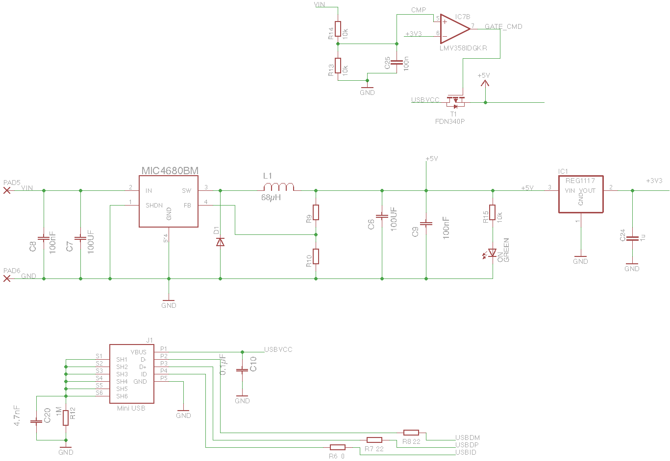
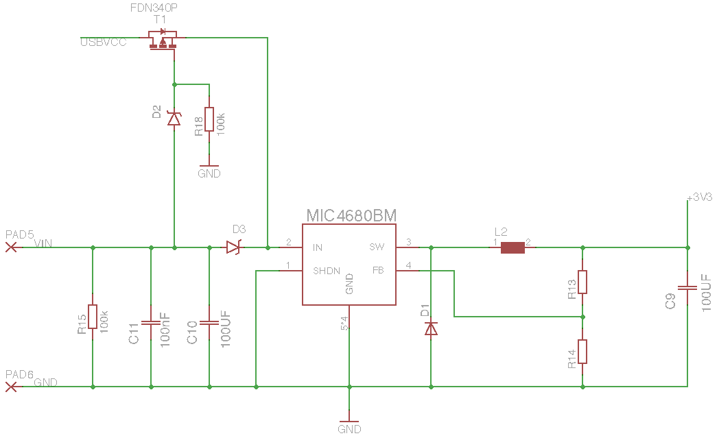
I have come up with a pre regulator circuit using a MIC4680BM which brings VIN down to 5v. I then have another regulator which brings 5v down to 3.3v.
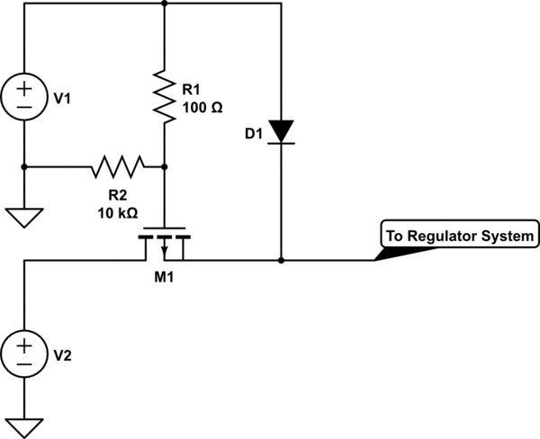
I have used part of the circuit that switches from VIN to USB from the Arduino Uno because this is the simplest application which is most similar to mine.
Their mosfet switch takes VIN though a voltage divider, I need a way to apply VIN to the mosfet which is always above 3.3v and not greater than 5.5v.
My questions would be:
Is this circuit going to work? (Providing I sort the voltage divider problem).
Could I just replace the voltage divider with a separate LDO circuit to take VIN to 5v solely for use as the input for the LMV358 (IC7)?

+5Vline. Your100µFcap will be problematic when you attach it to a PC or hub. \$\endgroup\$