5
\$\begingroup\$

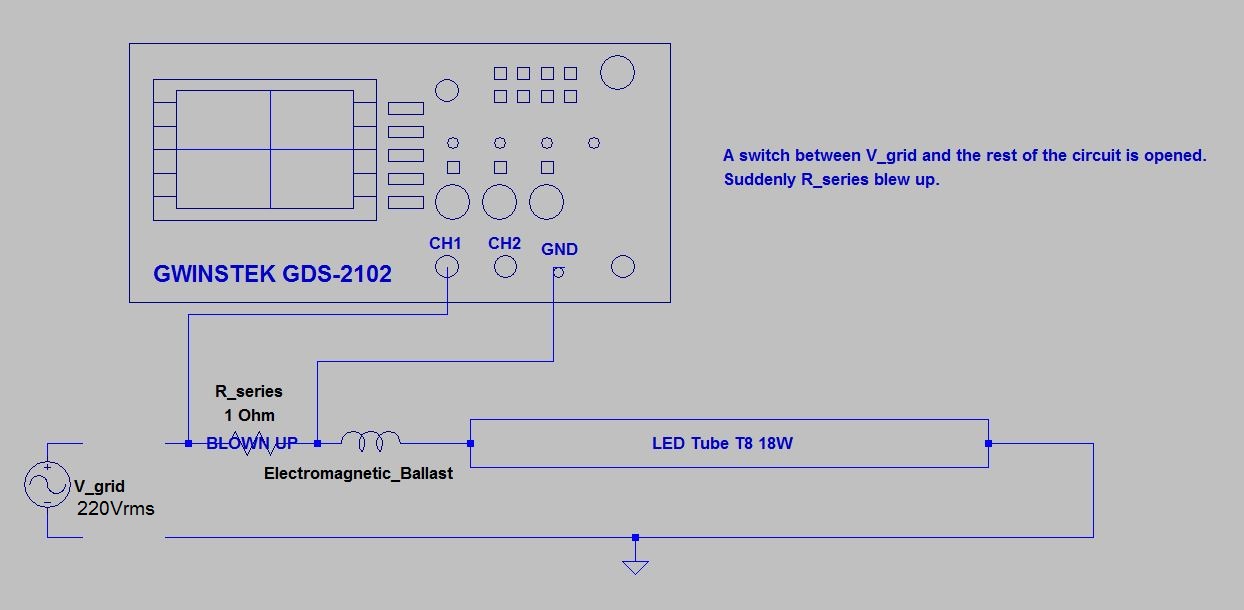
I want to see the input current waveform of an LED T8 18W. An EM ballast is purposely placed in series with the lamp. I don't have a power analyzer. What's available is a GDS-2102 oscilloscope. So I connect 1 Ohm resistor in series with the lamp. The waveform of the voltage across the 1 Ohm resistor should match the waveform of the input current.

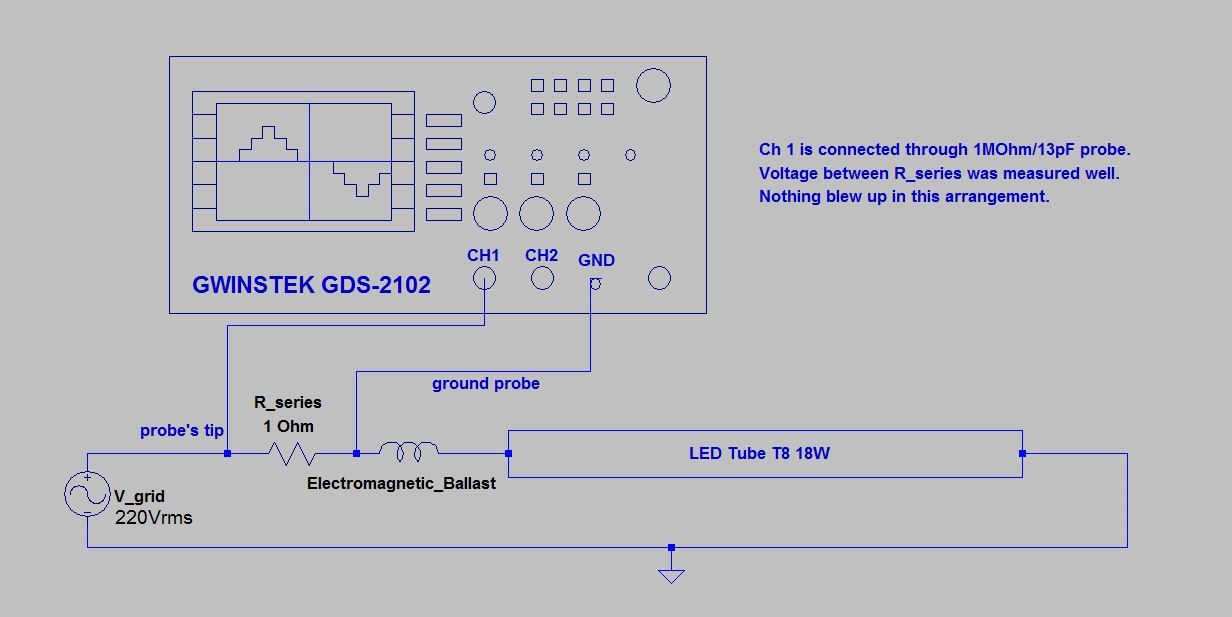
Nothing Blew Up

I put the oscilloscope probe and its ground probe across the resistor's terminals. And it works, a waveform I believe typical of input current of LED lamp is shown in the screen.

Then I open a switch connecting the grid to my experimental circuit with the probe still in their position. Suddenly the 1 Ohm resistor blew up. What is happening?

Rseries Blew Up

\$\endgroup\$
6
  • 8
    \$\begingroup\$ The ground on the oscilloscope is Mains Earth. You shouldn't be using scope probes like this. If you want to measure a signal which is not referenced to ground you either need a differential probe or to use both channels and make the oscilloscope do subtraction. \$\endgroup\$ Commented Feb 9, 2016 at 14:29
  • \$\begingroup\$ For further information search for a few youtube videos on "how not to blow up my oscilloscope". Quite a few good ones. Btw. I didn't know ltspice has oscilloscope models... \$\endgroup\$
    – PlasmaHH
    Commented Feb 9, 2016 at 14:33
  • 3
    \$\begingroup\$ Dave Jones has a video blog dedicatet to this topic, EEVblog #279 – How NOT To Blow Up Your Oscilloscope!. \$\endgroup\$
    – hlovdal
    Commented Feb 9, 2016 at 14:43
  • \$\begingroup\$ The oscilloscope in the figures were drawn using text, lines, rectangles, and circles in LTSpice. \$\endgroup\$ Commented Feb 9, 2016 at 16:18
  • 1
    \$\begingroup\$ Do yourself a favor and get an isolation transformer. Isolation transformers are to be used ONLY on the Device Under Test (DUT) - not on the oscilloscope. An isolation transformer lets the reference voltage of the DUT float so it no longer references earth ground. This means if you touch the DUT and the oscilloscope chassis you won't get a nasty surprise! You do NOT want to put the DUT on the oscilloscope because then the O-scope will float at whatever potentially dangerous voltages your probes come in contact with - making it dangerous if you touch that large metal case! \$\endgroup\$
    – Ramrod
    Commented Feb 9, 2016 at 22:35

1 Answer 1

10
\$\begingroup\$

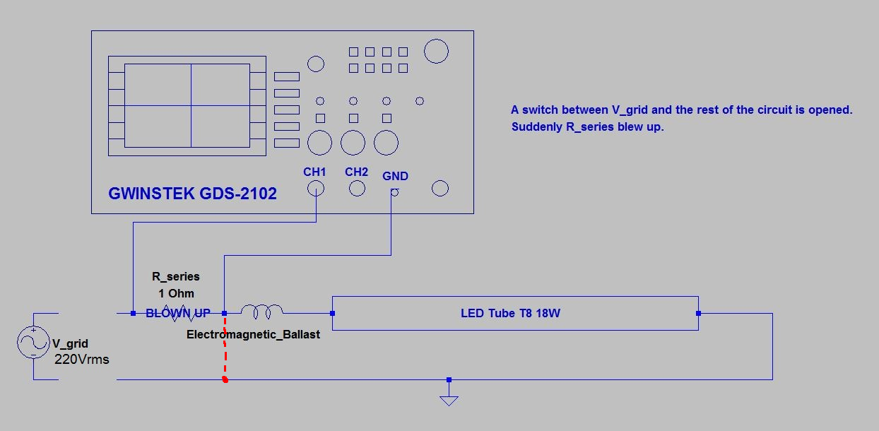
@Tom Carpenter's comment is correct. All oscilloscopes are "mains-Earth" grounded. Which means that the ground lead is connected to the ground pin of it's power plug. So what you actually did was this:

Shorting out resistor

The ground lead always must be connected to the actual ground of the circuit under test when using an oscilloscope.*

*Unless you use an isolation transformer on the device under test, with NO chassis or Earth ground.

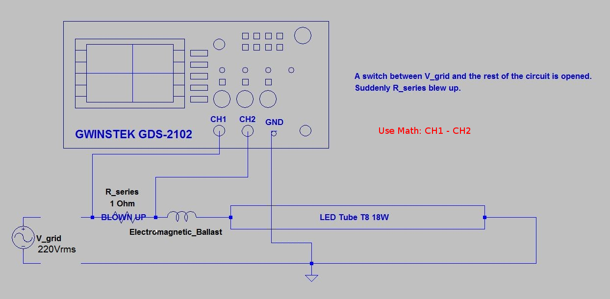
Also what Tom means by "making the oscilloscope do subtraction" is to connect two channels across the resistor, and grounds to actual ground. On the display will be two waveforms. Enter the "math" function of the oscilloscope, and instruct it to subtract channel 2 from channel 1. The result will be the difference between the two, which is the voltage across the resistor.

No Blow Up

\$\endgroup\$
7
  • 1
    \$\begingroup\$ With no voltage source from the grid, where did the energy that blew up the R_series come from? I've seen that this LED tube contains several electrolytic capacitors in its driver. Did the energy come from these capacitors? \$\endgroup\$ Commented Feb 9, 2016 at 16:11
  • \$\begingroup\$ @QelopinUacel How much do you know about the switch you opened up? Was it a double-pole switch as the diagram seems to indicate? Could it have been single-pole? \$\endgroup\$ Commented Feb 9, 2016 at 17:13
  • \$\begingroup\$ The switch must be wired in such a way that "open" was not quite accurate. Is there a name, part number for the switch? And how was it wired? \$\endgroup\$
    – rdtsc
    Commented Feb 9, 2016 at 18:21
  • 2
    \$\begingroup\$ "All oscilloscopes are "mains-Earth" grounded." most are and you should certainly assume a scope is until proven otherwise but scopes with non ground-referenced inputs do exist. \$\endgroup\$ Commented Feb 9, 2016 at 20:19
  • 1
    \$\begingroup\$ I got a probably good solution. I've tried using the subtraction but it didn't give a good result because the resolution is too low. What I found to be working is to place one terminal of the R_series at the ground and the other at the LED terminal. Then, the ground probe is connected to neutral and the Ch 1 probe is connected to the R_series's terminal which is connected to LED's terminal. Doing this is way, nothing blew up. \$\endgroup\$ Commented Feb 10, 2016 at 7:14

Your Answer

By clicking “Post Your Answer”, you agree to our terms of service and acknowledge you have read our privacy policy.

Not the answer you're looking for? Browse other questions tagged or ask your own question.