3
\$\begingroup\$

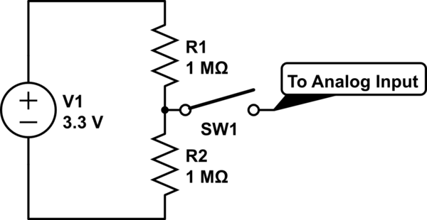
I have an Arduino and am trying to measure the voltage across R1. To do this I am connecting SW1 to an analog input. Using a multimeter I measure the voltage across both R1 and R2 to be 1.56V which is what I expect.

However, when I close SW1 the voltage across R1 jumps to 1.83V - why is this?

schematic

simulate this circuit – Schematic created using CircuitLab

\$\endgroup\$
2
  • 2
    \$\begingroup\$ What is the input impedance of that analogue input ? And that of your multimeter? \$\endgroup\$
    – PlasmaHH
    Commented Feb 15, 2016 at 10:26
  • \$\begingroup\$ Are you sure you have initialized the Arduino's analog input properly ? Sometimes you have to read the value twice to get the Arduino's ADC to initialize properly. What are you using as the reference voltage for the ADC, in this case you should use the supply voltage of 3.3 V as the reference voltage, not the internal reference voltage as that one is lower than 1.56 V. I'm assuming the GND of your Arduino is also the ground of this circuit, if not how do you connect the Arduino. Are you also using the 3.3 V supply to feed the Arduino ? \$\endgroup\$ Commented Feb 15, 2016 at 10:35

3 Answers 3

9
\$\begingroup\$

You have a very high source impedance (we normally keep this quite low).

The AVR ADC input has this general structure: AVR ADC input
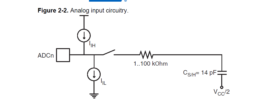
There will be some leakage current flowing either in or out of the pin and the total leakage is represented by I(ih) and I(il); assuming I(ih) is larger than I(il), then some extra current will flow into the lower resistor, thereby raising the voltage you measure.

In this case, that extra current looks like 270nA, a not unexpected value.

High source impedances are a well known source of ADC errors.

Note that connecting a high impedance source to an analogue input that has some leakage (and can be in either direction, generally specified as +/- something, usually in the order of microamps) will change the voltage you read across the resistor to a higher or lower voltage, depending on whether the effective leakage is sinking or sourcing current.

I would recommend this thread to understand the pain input leakage current can cause.

As noted, you can use a buffer amplifier to go from a high impedance world to a low impedance one (preferred in ADCs), but you need to ensure that the input offset current (the analogue of leakage current above) is low enough such that

R(source)*I(offset)

does not cause a significant error.

Most rail to rail input amplifiers have a dual input stage, but the input bias current is usually significantly different across the input stages; input offset current is usually directly related to input bias current. This simply means you need to be careful in the selection of such a buffer amplifier.

Another excellent reference on input bias current.
\$\endgroup\$
1
  • \$\begingroup\$ The high source impedance problem can be fixed by either using a lower impedance source (obviously), or adding a buffer amplifier between source and ADC. This can be implemented using a single op-amp. \$\endgroup\$
    – Rainer P.
    Commented Feb 15, 2016 at 12:13
2
\$\begingroup\$

Probably is the impedance of the analog input, you need to open the switch and measure the impedance of the analog input. If it is the case, you'll measure the value of 1,2 Mohm.

\$\endgroup\$
1
\$\begingroup\$

According to ATMega328 datasheet, input impedance on analog pin should not be higher that 10k ohms. Replace the 1M resistors with 10k and you should be good.

\$\endgroup\$

Your Answer

By clicking “Post Your Answer”, you agree to our terms of service and acknowledge you have read our privacy policy.

Not the answer you're looking for? Browse other questions tagged or ask your own question.