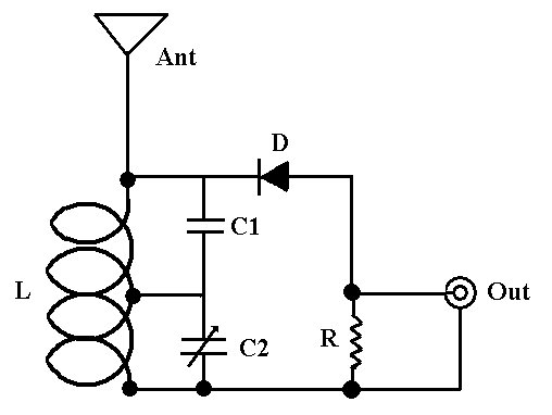
I'm intrigued by the second circuit in Spehro's answer and/or it's precursor (FM Crystal Radio) https://electronics.stackexchange.com/a/217086/33670
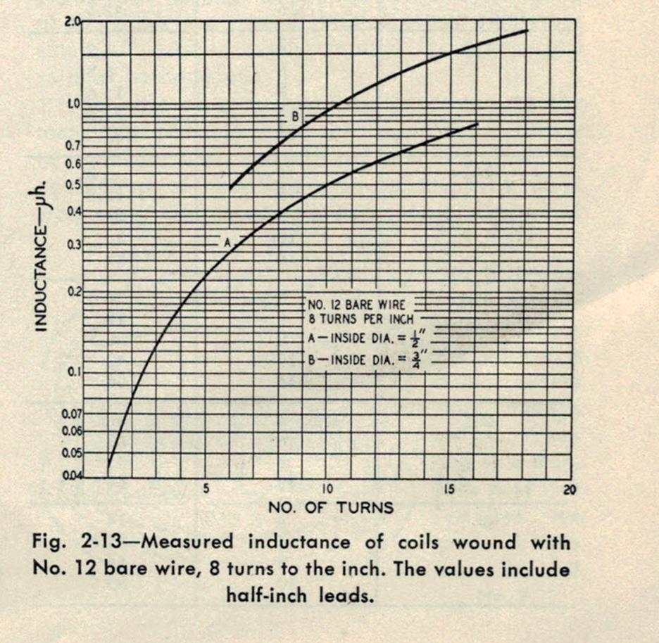
But I don't happen to have any 18 Ga solid wire, while I have a vast excess of 14 Ga and 12 Ga solid wire as construction byproducts.
The two versions of this circuit at the linked page call for 4 or 5 turns of 18 Ga (1.02 mm dia.) wire with a 12mm inside diameter.
That calculates out to 343 nH or 537 nH when I find a coil calculator that takes wire diameter as an input. Changing to 12 Ga (2.05 mm dia.) lowers it to 285 nH to 445 nH.
Using 12 Ga, if I increase the diameter to 16.05 mm (i.e. a 14mm ID) this seems to restore (nearly) the original inductance values - but then I realize that the coil calculator I'm using has no entry for overall coil length, and thus is probably assuming a close-wound coil, which these are distinctly not.
I find other calculators that let me play with length of the coil (which I note is not specified in the source, unless I'm missing it, though it can be ballparked from the stated inside diameter and photographs) but they don't have wire diameter as a variable. Nor do many of the formulas I find given on various sites. I begin to plumb the depths of what I don't know about inductance, and what effect wire diameter has on it.
Going with one of the "no wire diameter" coil formulae, 86 nH to 135 nH at D = 13mm (the original, approximately) assuming the coil length is 25 mm. If it's 15mm, 128-200 nH. Formula I'm using is $$ I (uH) = {0.394*(Coil Radius In cm)^2*(Number of Turns)^2 \over (9*Coil Radius In cm)+(10*Coil Length In cm)} $$
Seems for 22 cm of straight wire (about enough to make the longer coil), "self-inductance" for 18 Ga is 264 nH and 12 Ga is 234 nH - not a lot of difference - 30 nH or 13%-ish. But either (rather than the difference between them) is also somewhat more than the "coil calculation" gives for the coil, in this instance. If "wire-diameter self inductance" for a given length of wire simply adds to coil inductance, it seems to be somewhere between "make small adjustment" or "lost in the noise" - if I get this correctly, which I very well might not. For self-inductance I'm simply using several web calculators that seem to agree, I have not transcribed that one into a local spreadsheet yet.
So, is that the way it works when changing wire sizes for a given widely-spaced coil - (simple addition of self-inductance for a given length of given size wire to the coil inductance for a given coil inductor with no wire diameter specified) or not?


