5
\$\begingroup\$


I am using Pololu's sharp infrared sensor board part# GP2Y0A60SZLF and I am trying to minimize the noise caused by the sensor on the voltage supply as much as possible.

I have made a filter and voltage regulator circuit as shown below, The IR sensor and the filter PCB are directly connected together. The output is carried out via a wire 7" long from the filter circuit as shown to a main PCB that has another RC filter (R2,C10) filter schematic Here is the scope shot at the 6-12v supply terminal. The spikes below are 1khz, 46mv p-p. Scope Probe VDD
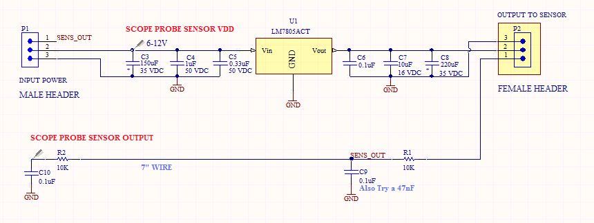
What do you suggest to clean the supply line below?

I am also including the waveform on the sensor output.

Sensor Output

\$\endgroup\$
12
  • \$\begingroup\$ Normally I would have a really had time caring about 46mVpp of noise on the input of a regulator. Does it actually make its way to the output? Is it really a problem, or are you trying to minimize it to minimize it? \$\endgroup\$
    – Matt Young
    Commented Feb 16, 2016 at 18:51
  • \$\begingroup\$ Hi Matt, it does make it's way to the output and that's one problem. I am planning to build 12 of these feeding off from the same supply line. Right now I can only turn on one at a time because of the noise I would get on the supply line. If I can manage to clean out the supply line as much as possible then I can turn on all sensors at the same time. \$\endgroup\$
    – Rocky79
    Commented Feb 16, 2016 at 19:02
  • \$\begingroup\$ In your schematic you say "scope probe sensor VDD", but isn't your sensor VDD really at C8? What does the voltage look like there? \$\endgroup\$ Commented Feb 16, 2016 at 20:11
  • \$\begingroup\$ @DigitalNinja What matters to me is the effect of the sensor on the power line which is the input of the regulator. I will have to check the scope output at C8. \$\endgroup\$
    – Rocky79
    Commented Feb 16, 2016 at 20:16
  • \$\begingroup\$ Okay, I thought you were worried about it the other way around (the input power affecting the sensor output) - which is what I think would be a normal concern. \$\endgroup\$ Commented Feb 16, 2016 at 20:19

1 Answer 1

2
\$\begingroup\$

This sensor draws like 300mA in bursts, likely you can see that on the power. I have had a similar problem with driving servos, which made huge spikes on the power line when powering from a lab psu.

I suggest to:

  • power this all with a battery with small internal resistance, i.e. alkaline AA cells, or LiPo
  • increase c3 to at least 470uF or 1000uF
  • (might try LC filter on the power lines)

The output signal is not bad with 30mV of noise. Your idea of the RC filters look correct. I'd give also a try with bigger C and smaller R, like R of not more than 1k, and C of some microfarads.

\$\endgroup\$
2
  • \$\begingroup\$ Thank you for the suggestion. I ended up turning on one sensor at a time rather having them all on ( 12 sensors). The 30mv noise was acceptable for my application, so it turns out it's not too bad. \$\endgroup\$
    – Rocky79
    Commented Mar 17, 2016 at 23:45
  • 1
    \$\begingroup\$ Oh 12 sensors x 300mA! That is quite a load with spikes! Glad you made it working! \$\endgroup\$
    – Gee Bee
    Commented Mar 18, 2016 at 0:21

Your Answer

By clicking “Post Your Answer”, you agree to our terms of service and acknowledge you have read our privacy policy.

Not the answer you're looking for? Browse other questions tagged or ask your own question.