2
\$\begingroup\$

So I have an interesting challenge. I have an LCD screen from a laptop which I am driving with a control board. The problem is the backlight needs around 19 volts to run while the control board I have is designed for LCD panels with a 5 volt backlight. Everything else runs fine, just not the backlight. I have a 19 volt power supply that I intend to run everything off of (the 5v control board will be powered of a buck converter from this 19v source). The problem is, when the control board is off or in power saving mode, it is supposed to cut power to the backlight, but since I am driving it directly off the 19v power supply, it stays on. To solve this problem I acquired myself a TIP31AG power transistor from the local radio shack (yes they do still exists) assuming that it could be used like a relay, or atleast in the same situations. As you can imagine this turned out not to be the case.

The Problem:

  • I have a 19v load of an unkown and probably variable current draw and resistance (it has a separate PWM brightness control which probably varies things).
  • I have a 5v control wire which can provide a decent amount of current (greater than logic level that is)
  • I need to control the VCC into the load (not the ground connection, due to the way the control board works)
  • I have a TIP31AG power transistor, and all the tutorials I have looked at have their TIP31 (which is NPN btw) downstream of the load (that is between the load and ground)

Can this be done with my TIP31 or do I need a TIP32 (the PNP variant) and another PNP control diode to control the load on the VCC side?
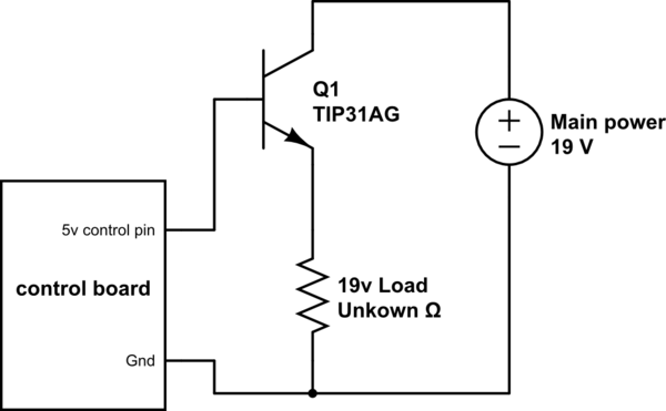
schematic

simulate this circuit – Schematic created using CircuitLab

\$\endgroup\$
4
  • 3
    \$\begingroup\$ please look into a "high side power switch" using PNP BJTs or P-channel MOSFETs. \$\endgroup\$
    – KyranF
    Commented Feb 18, 2016 at 22:00
  • 1
    \$\begingroup\$ from another question on this site.. i.sstatic.net/8PxZ6.png \$\endgroup\$
    – KyranF
    Commented Feb 18, 2016 at 22:01
  • \$\begingroup\$ Use a high side switch as Kyran says, unless you have independent access to the return from the +19 (it's not common with ground), in which case you can follow Olin's method. \$\endgroup\$ Commented Feb 18, 2016 at 22:03
  • \$\begingroup\$ What exactly do you mean by independent access to the return? the screen backlight has a ground wire that is directly connected to the ground for the rest of the screen which in turn must be directly connected to the power supplies ground. \$\endgroup\$
    – pop1040
    Commented Feb 18, 2016 at 23:14

1 Answer 1

0
\$\begingroup\$

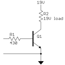
It seems you want to switch the 19 V backlight on/off with a 5 V signal. This can be done with a NPN power transistor, but not the way you show. The problem is that you are running it in emitter follower mode. The output voltage will be the control voltage minus the B-E drop, which is around 700 mV. In your circuit, the 19 V load will only get about 4.3 V.

To fix this, run the transistor in common emitter mode:

You haven't said how much current the 19 V load requires, nor provided a link to the transistor datasheet, so we can't tell what the base current needs to be. I arbitrarily chose 10 mA. If the transistor has a guaranteed gain of 30 in this case, then this supports up to 300 mA load current. You also haven't said what the current capability of the digital output is, so I can't even say whether this is possible or not.

If the digital output can't supply the load current divided by the transistor gain, then you need a higher gain transistor, or a second transistor to provide more gain.

Another approach would be to replace the NPN transistor with a N channel MOSFET, like the IRLML2502. In that case, connect the gate directly to the digital output without R1 between.

Added

Argh! You now say that the 19 V load is connected to ground and you can only switch the high side. Thanks for the wild goose chase.

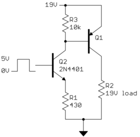
Here is something that should work:

Q2 becomes a controlled current sink depending on the digital signal. When the digital signal is at 0 V, it is off. R3 is enough to overcome whatever base leakage Q1 might have and make sure it is off. This turns off power to the high side of the load.

When the digital signal is at 5 V, the base of Q2 will be at about 4.3 V. R1 is therefore causing about 10 mA to flow, most of which will come from the collector of Q2. Most of that will come from the base of Q1. If Q1 has a gain of 30, then it can support up to about 300 mA of load current.

In this case the drive capability of the digital signal is of little concern since Q2 provides additional gain. Let's say it has a gain of 50, so that means it only requires the digital output to source 200 µA when high. It would be very unusual for a 5 V digital output to not be able to do that.

\$\endgroup\$
1
  • \$\begingroup\$ Thank you! So can I reuse my TIP31 or do I need all new transistors? Also is Q1 my NPN transistor or a PNP transistor? same for Q2. Also what is this about independent access to the return? \$\endgroup\$
    – pop1040
    Commented Feb 18, 2016 at 23:47

Your Answer

By clicking “Post Your Answer”, you agree to our terms of service and acknowledge you have read our privacy policy.

Not the answer you're looking for? Browse other questions tagged or ask your own question.