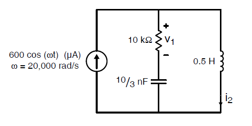
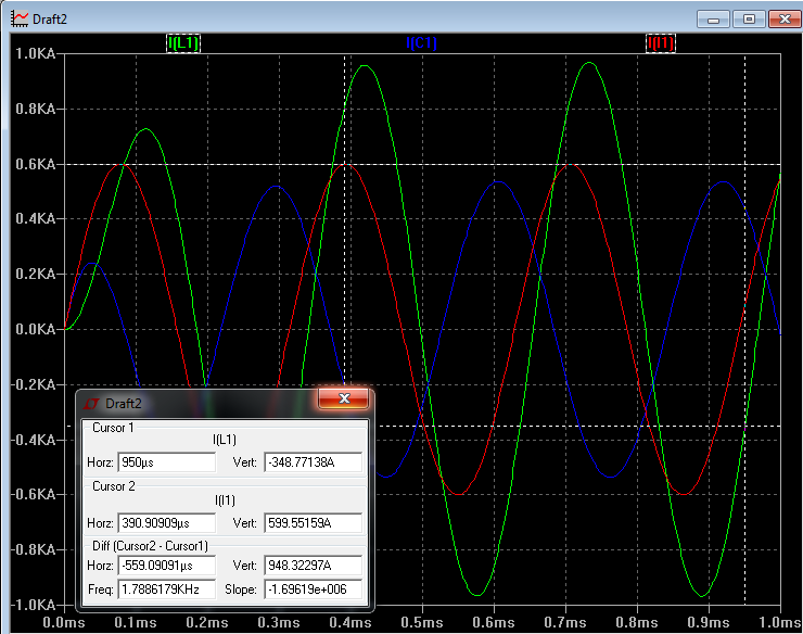
You seem to have in mind what you learned about DC circuits with resistors. There is some source that forces current through some resistors, and the current in each resistor can never exceed the current provided by the source, because the source current is divided among the resistors.
The key concept that makes this work for DC circuits is that pushing current into a circuit is equivalent to pushing energy into that circuit, which is something a passive component obviously cannot do. The point about the energy is still valid in AC circuit analysis, but there can be current sources that are not energy sources, if current and voltage are 90 degrees out of phase.
In your circuit, the current through the inductor is sourced from both the current source and the capacitor. On the other hand, if you calculate the energy consumed by the only lossy element in your circuit (the resistor), it should match the energy provided by the only energy source (the AC current source) exactly.
It is interesting to understand that the combination of an element with current and voltage in phase (the resistor in your circuit) and an inductor in series is how fluorescent lamp ballast circuits work (at least in 220V countries). In big industrial lighting installation, capacitors are paralleled to compensate for the inductance, so the impedance gets real. In this practically proven circuit, the lamp current (at 100V) exceeds the supply current (at 220 to 240 volts), so transmission losses between the utility company and the lighting installation is minimized.


