12
\$\begingroup\$

While studying about capacitors, I came across with an explanation talking about "jumping up and down when a capacitor separating two stages". I understood from several articles here that capacitors block DC when it is fully charged and that the idea of 'charging and discharging' of capacitor.

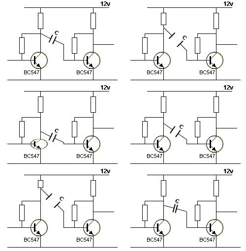
'This page' explains

  1. If a capacitor has the negative lead connected to the 0v rail, it will charge and discharge
  2. If a capacitor is NOT connected directly to the 0v rail, it will JUMP UP AND DOWN.

and with the following figure, says

the capacitor will 'fall'and the voltage on the negative lead can actually go below the 0V rail

where I totally lost my understanding.

enter image description here jumping cap
(source: talkingelectronics.com)

(please refer to '4. A capacitor separates two stages' on 'the linked page.')

The pages explains that

By knowing how much a capacitor jumps-up-and-down, you can "see" a circuit working. and here my questions came.

  1. I can't understand the difference between 'charging/discharging' and 'jump up/down'. I thought even though it's not directly connected to 0V rail, still depending on its reference voltage, it can be charged and discharged. What is the difference in those two expression to comprehend their meaning?
  2. What happens when capacitor jump up and down?
  3. How can I calculate the amount of the 'jumps'?
\$\endgroup\$
11
  • 12
    \$\begingroup\$ "The skill of being able to "see" a capacitor "jumping up and down" in a circuit has never been described before in any text book or covered in any lecture and that's why so few people really understand how a circuit works." Well, I'm glad the author of that page has cleared that up for us. Honestly, I suggest you look for a different page offering a more coherent explanation. For "jumping up and down", see "coupling capacitor" and "charge pump". \$\endgroup\$ Commented Mar 7, 2016 at 12:17
  • 25
    \$\begingroup\$ Sounds to me like the author was trying to describe something he doesn't quite understand himself. \$\endgroup\$
    – brhans
    Commented Mar 7, 2016 at 12:20
  • 10
    \$\begingroup\$ That would be your Mexican Jumping Capacitor. It's actually a larval moth living inside the capacitor that will move around as the circuit heats up. If you forget to tie the capacitor to ground, the motion can get quite dramatic. As a trivial aside, it can be demonstrated that this phenomenon is behind the colloquial use of the term "bug" in a circuit. \$\endgroup\$ Commented Mar 7, 2016 at 16:05
  • 7
    \$\begingroup\$ Yep, just as I thought. Talkingelectronics. Colin Mitchell, the creator of the site, is a known moron who doesn't know what he's talking about. He's been banned from multiple fora and has been known to steal others' designs and pass them off as his own. He claims to have an engineering degree but a member on one of the forums that banned him did some research (contacted the university he claimed to have graduated from) and they had no record of him. Go figure. Don't trust anything you see on TalkingElectronics \$\endgroup\$
    – DerStrom8
    Commented Mar 7, 2016 at 16:31
  • 5
    \$\begingroup\$ An electrolytic capacitor would certainly jump if you reverse biased it, but beyond that... \$\endgroup\$ Commented Mar 7, 2016 at 18:45

5 Answers 5

20
\$\begingroup\$

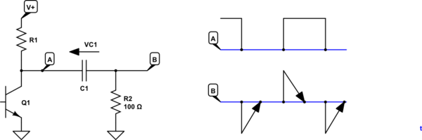
What the author is describing in that circuit is that if the voltage on the left side of the capacitor suddenly changes level, the voltage on the right side will change by the same amount.

schematic

simulate this circuit – Schematic created using CircuitLab

Figure 1. Square-wave passed through a capacitor. (Please excuse arrows as RC discharge curves.)

With the circuit schematic shown above:

  • Initially 'A' is high and 'B' is at 0 V.
  • When Q1 switches on 'A' is pulled ("jumps" in the author's parlance) to 0 V.
  • At the instant of switching the voltage across C1 is V+ so when 'A' is pulled low 'B' is pulled low as well. i.e., Both sides "jump" together as neither side is grounded.

In the case of a filter capacitor one side is usually grounded so this effect is not seen.

I find it useful in circuit analysis to think of the capacitor's action in this fashion. I figure out what the steady-state voltage is across the capacitor and what will happen the right side when the left side suddenly changes voltage.

Simulation waveforms

schematic

simulate this circuit

Figure 2. Test schematic.

enter image description here

Figure 3. 500 Hz, 1 µF, 100 kΩ.

Figure 3 shows what happens when the capacitor is feeding a high resistance load.

  • On the first rising edge of the input the output "jumps" up with it. R1 starts to discharge the right side, however, and at the end of that half-cycle the voltage has drooped a little.
  • On the first falling edge the input drops by 1 V and so does the output. Since the starting point is about +0.9 V the output drops to -0.1 V.
  • This process continues and after a while the waveform settles down centred about the zero-volt line.

enter image description here

Figure 4. 500 Hz, 1 µF, 1 kΩ.

  • Decreasing R1 to 1 kΩ causes the effect to be more pronounced as the capacitor discharges and charges more quickly. Notice how the waveform has settled down after a few cycles.

enter image description here

Figure 5. 500 Hz, 1 µF, 100 Ω.

  • In Figure 5 R1 has been decreased to 100 Ω and we can see that the output waveform has become much more spikey. We can also see that it no longer reaches the +1 V level because the load resistor is so low.

This explanation is deliberately non-mathematical and is intended to give you some mental picture of what's really happening. If you study the maths some more and figure out where the current is flowing you should be able to get a good grasp of how it works.

Simulation

Linear Technology (chip-maker) have their LT Spice simulator available as a free download. I recommend you try this to assist in your learning and understanding.

\$\endgroup\$
7
  • \$\begingroup\$ thank you for your explanation. This makes sense of the parlance "jumps". I understood 'A' is pulled to 0 V when Q1 is on. But, my another novicelike question for the explanation is, why is 'B' pulled low by the same amount as well? \$\endgroup\$
    – Hwi
    Commented Mar 7, 2016 at 13:50
  • \$\begingroup\$ I tried to think it as AC coupling for the instant time of switching, but, if it were AC coupling, shouldn't the voltage on both side be same? \$\endgroup\$
    – Hwi
    Commented Mar 7, 2016 at 14:02
  • \$\begingroup\$ Your second comment is exactly right in that the AC voltage will be the same on both sides but the point is that there is a DC offset. So to answer both comments, in the case of a step change the right-hand side changes by the same amount, keeping the DC offset. As my very crude diagram attempts to show, the charge may then bleed off, gradually eliminating the DC offset. \$\endgroup\$
    – Transistor
    Commented Mar 7, 2016 at 14:08
  • \$\begingroup\$ Thank you for the comment. I understood after bleeding off, the DC offset eliminates and eventually both will be the same potential. I was also wandering about the instant moment of Q1 ON, why that DC offset is being kept and both sides of the capacitor pulled low in your explanation. If my following understanding is wrong, please comment. \$\endgroup\$
    – Hwi
    Commented Mar 7, 2016 at 15:17
  • \$\begingroup\$ The reason that the potentials of both side of the capacitor drop together keeping DC offset is that the capacitive reactance Xc=1/(2pifC) is small enough because of the short instant time, thus high f. However, if either the capacitance is small enough or the changing time is long, Xc is relatively big, so the right side of the capacitor would not be pulled as much as the DC offset, and would almost look like it stays at 0 V. \$\endgroup\$
    – Hwi
    Commented Mar 7, 2016 at 15:17
24
\$\begingroup\$

Forget about it. Move on. The author of that web site seems to be struggling with what a capacitor is himself. He has formed little mental cruxes in a attempt to demystify these capacitator thingies to himself, much like early people created various myths to explain things they didn't understand either. He then tries to explain the mysterious beast to you using his personal myths. It doesn't work well. Like I said, forget about it and move on.

I think his vision of "jumping around" is really referring to the common mode voltage, such as when used to pass a signal, which is different to him than when used for power supply smoothing. Don't get hung up on this guy's personal mythology.

\$\endgroup\$
3
\$\begingroup\$

I think what the author wants to visualize is the coupling of two nodes in a circuit by a capacitor.

In order to change the voltage across a capacitor a current through the capacitor is required. If the capacitor is big or the current small, the voltage change will be slow.

In this case, if the voltage of one of the nodes changes the capacitor will act as a voltage source and the same change can be seen on the second node.

The situation the author probably imagines is a sudden drop of the voltage on one terminal of the capacitor that could push the other one below 0V.

\$\endgroup\$
1
\$\begingroup\$

I am still trying to wrap my head around capacitors, but if my half-understanding is on track, then maybe I can help someone in the same boat.

The basic deal with capacitors seems to be, they trade current for voltage: current can flow "through" a capacitor initially (really it's a matter of charge collecting on one plate and pushing charge away from the other plate), but the current drops off as charge collects on the plates, and in the end you're left with a voltage differential but no current. That's when the capacitor is fully charged. So for example, let's say you've got a capacitor coupling two circuits, one at a 5V point and the other at a 2V point. That means that, when the capacitor is fully charged, the charge on the capacitor plates amounts to a 3V drop across the capacitor.

I think -- I think -- the jumping is about this. Let's say that the first circuit moves quickly from 5V to 10V. The voltage across the capacitor is still -3V, so the other side of the capacitor likewise increases from 2V to 7V, initially at least. The parameters of your circuit may then cause the charge on the plates to flow in or out and change the voltage across the capacitor, so the 5V "jump" may be very very temporary. Maybe it will work out that the second circuit gradually pulls its side of the capacitor back to the 2V level, so when things settle again we've got a voltage drop of 8V. And then I suppose the voltage on the first circuit could suddenly drop back down to 5V, sending the voltage on the right to -3V until things re-settle again.

This sounds like a crazy outcome, but you know what it perfectly explains? The astable multivibrator. One of the features of the astable multivibrator is that, when the one transistor finally conducts, it throws a big negative voltage at the other transistor's base, and the only way I've been able to understand that is via what I described above. It's still counterintuitive as all heck to me, but I'm trying to come to terms with it.

\$\endgroup\$
1
  • \$\begingroup\$ You're thinking is on-track. Inductors like to keep current through them constant - in the short term, at least. Capacitors like to keep the voltage across them constant. \$\endgroup\$
    – Transistor
    Commented May 29, 2016 at 16:56
0
\$\begingroup\$

I find it useful to think about a coupling capacitor as a way to isolate stages so that the (DC) bias of one stage does not affect the (DC) bias of another, and as a "short" for the (AC) signals.
If the capacitor were a real short, it should be obvious that when one "side" of a short changes, the other "side" will also change by the same amount. What this means, is that if the left side of the capacitor "jumps" by +1v, the right side will also "jump" by the same amount (+1v). If the left side "drops" by -1v, the right side will drop" by -1v.

\$\endgroup\$

Your Answer

By clicking “Post Your Answer”, you agree to our terms of service and acknowledge you have read our privacy policy.

Not the answer you're looking for? Browse other questions tagged or ask your own question.