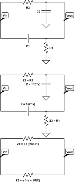
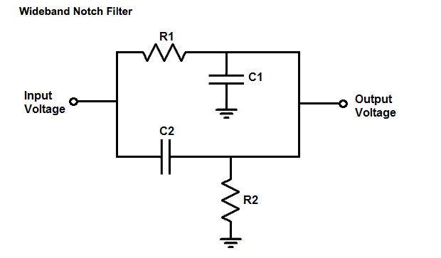
To find the transfer function of a circuit you need to be able to convert the circuit to a frequency model with the Laplace transform.
Capacitors become \$ Z = \frac{1}{Cs} \$
Inductors become \$ Z =Ls \$
Resistors become \$ Z = R \$
Then you can apply circuit theory and reduce the circuit just like they were resistors.
The high and low pass section treated like a resistor divider \$ Z = \frac{Z_{bot}}{Z_{top} + Z_{bot}} \$
(Zbot is the circuit element connected to ground)
With the starting values of the schematic I posted the low pass is: \$ \frac{R2}{R2 + \frac{1}{C2*s}}=\frac{s}{1 + R2*C2*s}\$
With the starting values of the schematic I posted the high pass is: \$ \frac{\frac{1}{C1*s}}{\frac{1}{C1*s}+R1}=\frac{s}{s+\frac{1}{R1*C1}}\$
If you want to further simplify this circuit the parralell resistor rule can be used:
\$ R_{total} =\frac{1}{\frac{1}{R_1}+\frac{1}{R_2}}\$
\$ Z_{total} =\frac{1}{\frac{1}{Z_1}+\frac{1}{Z_2}}\$
Z1 would be the lowpass and Z2 would be the high pass
\$ Z_{total} =\frac{1}{\frac{1}{\frac{s}{s+\frac{1}{R1*C1}}}+\frac{1}{\frac{s}{s+\frac{1}{R1*C1}}}}=\frac{C1*C2*R1*R2*s}{C1*R1 + C2*R2 + 2*C1*C2*R1*R2*s}\$
then you can substitute \$ s=j\omega = j2\pi f \$ to find the frequency parameters you want.

simulate this circuit – Schematic created using CircuitLab


