4
\$\begingroup\$

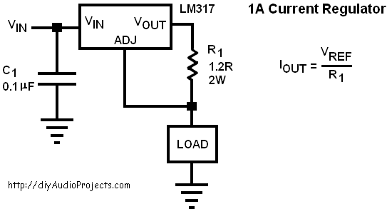
I want to control power RGB LEDs, for efficiency and safety they are better to be driven by a current source. I can use either linear or buck converters. I made a linear current source using LM317.

enter image description here

I PWMed the input (Vin) and it worked fine. Is it OK if I PWM the output(using a MOSFET right before the load)? As I learned in theory if the output is left open the output voltage reaches infinity (hear maybe a maximum of input voltage), so as I turn the MOSFET on a high voltage goes to the LED momentarily and might damage it after a while.

I think a decent step-down LED driver is PT4115E (Datasheet) it has a PWM pin. Are chips like this OK for driving LEDs that duty cycle may change several times per second?

\$\endgroup\$
1
  • \$\begingroup\$ What's wrong with controlling the input? Controlling the output seems more risky and less power efficient. \$\endgroup\$
    – horta
    Commented Mar 11, 2016 at 21:43

3 Answers 3

2
\$\begingroup\$

Assuming you do not want to modify your current source, and only want to modify the load: Instead of inserting the switch in series, it is more important to provide an alternate path for the current to take. If I understand you correctly, you are considering the schematic on the left. Replacing it with the one on the right should work better. Your control signal will be inverted; when the signal is high, the load will be shorted so not drawing current.

schematic

simulate this circuit – Schematic created using CircuitLab

\$\endgroup\$
2
  • \$\begingroup\$ If shorting the load is not allowed then you'd want to add a series switch to disconnect the load. But what you can also do is add a diode in foward in series with the load then when the shorting switch closes the diode will block any reverse current. \$\endgroup\$ Commented Mar 11, 2016 at 21:36
  • \$\begingroup\$ Thanks for you answer, It is an LED so shorting the load is not a problem but this way in case of a linear converter all the energy will be wasted, if it's a 12V supply and the current is 300mA it means 3.6W will be wasted during the time the LED is off! \$\endgroup\$
    – ahmadx87
    Commented Mar 12, 2016 at 6:02
1
\$\begingroup\$

Actual current sources are not even close to ideal. In real life, current sources are usually current-limited voltage sources. The only time you get a really high voltage from trying to cut off a current is when an inductor is involved.

Your circuit's output current will be constant unless the required voltage to maintain the current is higher than \$V_{IN}\$ minus a couple volts. If the load resistance is too high, the LM317 output will saturate near \$V_{IN}\$. So as long as your transistor switch can handle the full \$V_{IN}\$ voltage, you should be fine.

\$\endgroup\$
1
\$\begingroup\$

With the output side series switch the OP may be justifiably nervous about the instantaneous higher than rated voltage at the time of switch on. These can cause a current spike outside the safe operating range every time the load is switched on though not a problem usually for a filament bulb it can be a problem for an LED and certainly for a laser diode. If there is stray or unintended capacitance before the switch there may be more energy waiting to discharge repeatedly through the LED than is good for it.

The shunt switch to turn off the laser diode is used in sensitive applications and can be designed to drop the voltage to just below the operating voltage of the load for fast response (though even a low voltage will cause a little conduction and light with an LED, almost no laser action is achieved before the threshold current is reached). The shunt method obviously does consume the full load current at all times but in some situations this can be a good thing if you want your power supply to see a constant load, in a simple illumination scenario it is just wasted energy.

I would suggest that the sense pin of the current regulator be controlled. If this pin is driven to ground the regulator output voltage will be limited to 1.2V and through the shunt resistor it is unlikely to be able to pass much current through the LED that is held way below the rated forward voltage. A resistor (say 1 kOhm) to replace the sense terminal link and a open collector/drain output to pull it to ground.

EDIT:
Here is a thread that has gone through all the same iterations as the answers to this SEE question. I just found it using Google image search with the following search phrase lm317 current source switched.

They link to an image of a circuit that looks just like what I was suggesting. It was about the third image in the thread if the direct link does not work.

Further EDIT:
There are a number of regulators with a shutdown pin that may be even better suited to the task at hand. Parts such as LM2941, LT3022 and UCC281 may be worth checking out.

\$\endgroup\$

Your Answer

By clicking “Post Your Answer”, you agree to our terms of service and acknowledge you have read our privacy policy.

Not the answer you're looking for? Browse other questions tagged or ask your own question.