2
\$\begingroup\$

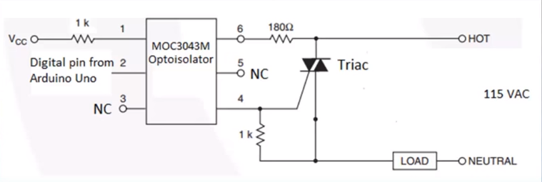
I am trying to simulate the operation of an optocoupler with a triac to trigger the triac using the AC current. I have come across a few circuits that are all similar:

enter image description here

My question is regarding the connection of pin 4 of the optical isolator to the load as well as the gate of the triac. Shouldn't it be connected to the gate only? Doesn't connecting it to the load by pass the triac and defeat the purpose of using a triac?

The configuration above works in the Multisim simulation but only because the current seems to be flowing through the 1k resistor; the triac doesn't switch on when I place an oscilloscope across it.

\$\endgroup\$

2 Answers 2

4
\$\begingroup\$

If the load current is extremely tiny then the triac may indeed fail to trigger. This is quite intentional, and the 1K resistor helps.

When the load resistance is low enough the current through the triac gate will exceed the trigger current and the triac will turn on near the zero crossing (see the MOC3043 datasheet for what 'near' means). Note that the current will flow primarily through the triac gate before it triggers and when that current exceeds about 1mA (due to the 1K resistor). After it triggers, the current flows through the triac.

Again, if the load resistance is low enough, the current through the triac will rise to a level that exceeds the holding current (see the triac data sheet) during the brief zero-crossing interval established by the MOC3043.

Only if both those conditions are true will the triac switch on properly for the entire AC half-cycle.

Suppose that the holding current of the triac is 50mA and the trigger current is 5mA, and that the zero crossing voltage is 15V (just picking some numbers). For the triac to trigger, the load resistance must be less than about 2K\$\Omega\$, and for it to stay on it must be less than about 280\$\Omega\$, which is about a 50W load on 115VAC.

\$\endgroup\$
3
\$\begingroup\$

The MOC3043M is a zero-cross triac driver. Internally there is some circuitry to allow switch-on close to zero-cross and inhibit it otherwise. This circuitry needs power and so the 1k resistor between the gate and the output allows the device to "steal" some power from across the main triac without actually triggering it (when it shouldn't).

If found the internal schematic for the G3MB-202P 5V input (Zero crossing and built in snubber) some time ago and it may help your understanding.

schematic

simulate this circuit – Schematic created using CircuitLab

Figure 1. Simple SSR has zero-cross on/off switching - EDN.

  • If \$V_{L1-L2}\$ is low (above but close to zero) and Q1 is turned on by photo-action from D1 then SCR1 will be triggered. This in turn will pass enough current through R6 to bring TRI1 gate voltage high enough to trigger.
  • When voltage exceeds a certain level Q2 will be biased on. The collector voltage will fall and there won't be enough to turn on SCR1.

The effect is that TRI1 can't turn on unless it is triggered close to the zero cross.

It should be fairly clear to you that this circuit requires some current to operate and that the 1k resistor in your diagram provides a path to neutral and through the load.

\$\endgroup\$

Your Answer

By clicking “Post Your Answer”, you agree to our terms of service and acknowledge you have read our privacy policy.

Not the answer you're looking for? Browse other questions tagged or ask your own question.