3
\$\begingroup\$

I have a Texas Instruments Tiva C-Series LaunchPad (Part Number: EK-TM4C123GXL). I've got the LaunchPad for only a month. Most recently, I used Energia to upload the following code into my LaunchPad:

https://gist.github.com/phil3c7r0n/4e22cd686ae196f92e6b

In my code, I used the following pins: PB_7, PE_5, PB_6, PB_4, PE_0, PD_0, PD_2

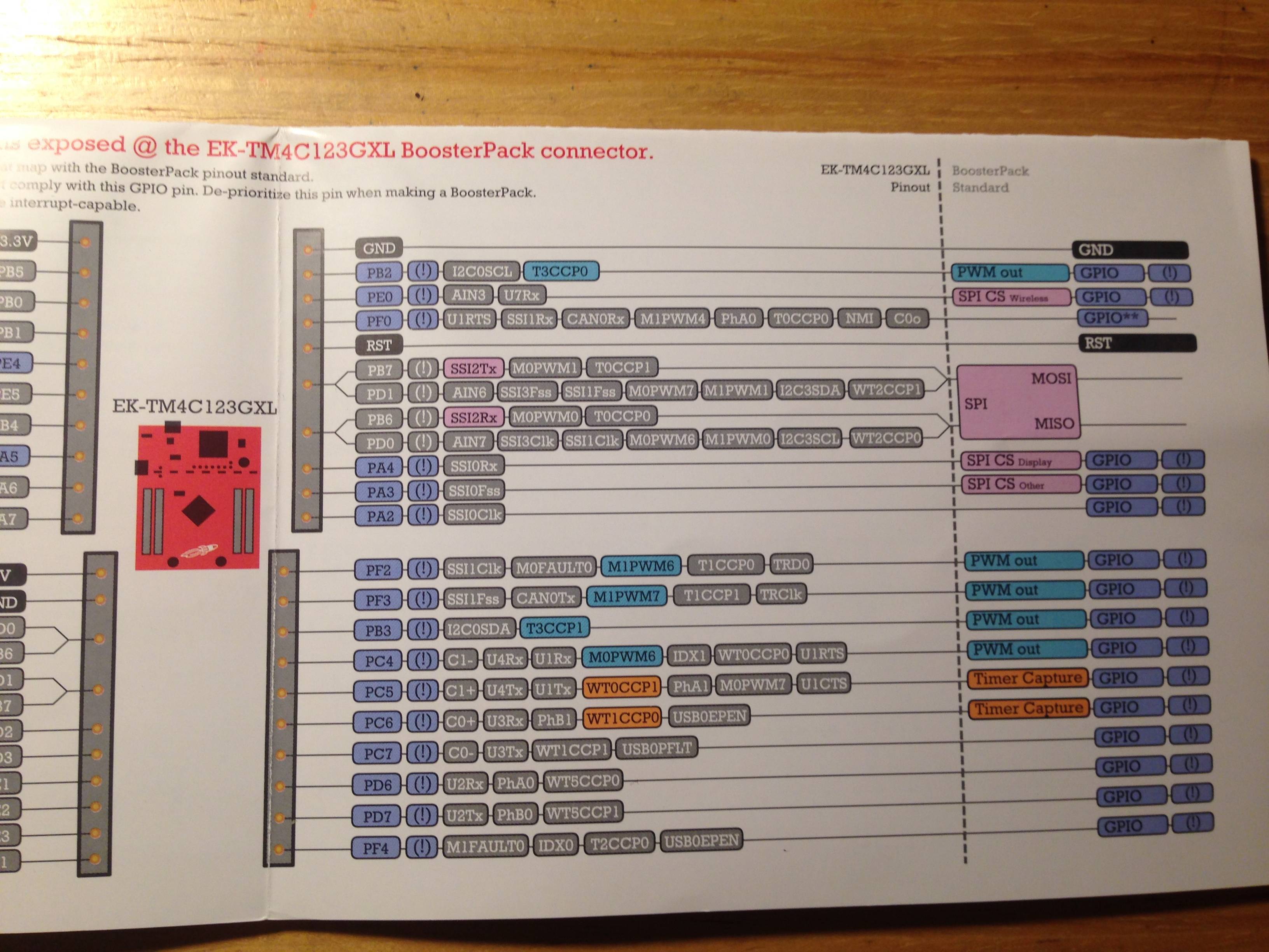
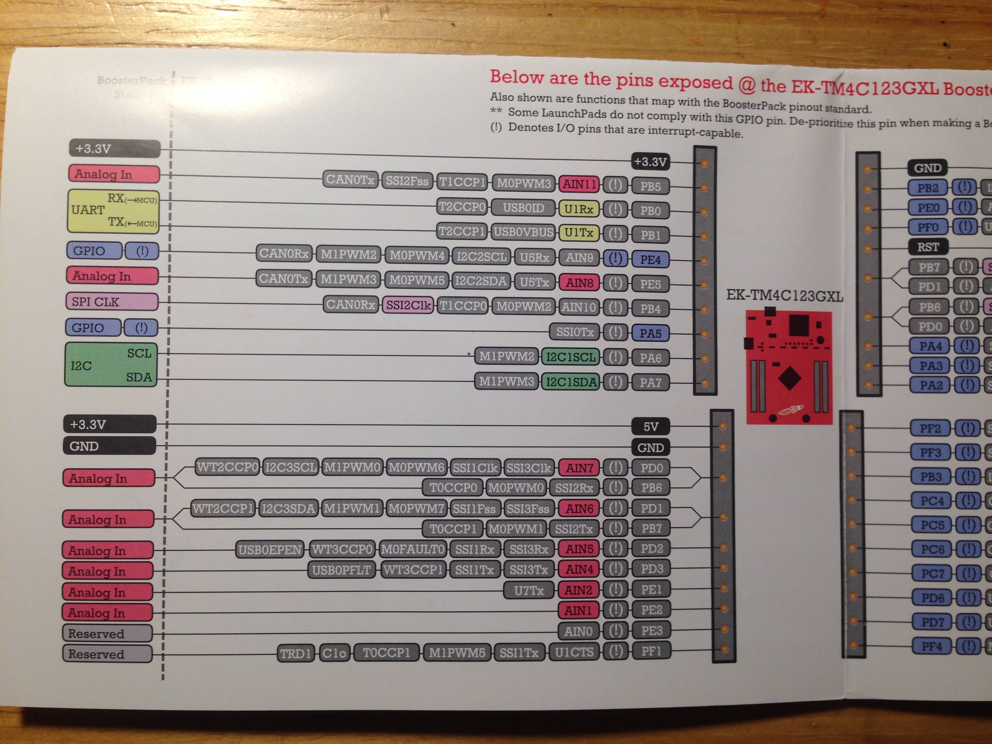
And here is the guideline of the LaunchPad:

enter image description here enter image description here

As you see, in my code I wanted to use PB_7, PE_5, PB_6, PB_4 as OUTPUT with Pulse Width Modulator (~PWM). However, for a stupid reason that I forgot about the guideline included in the LaunchPad's box, I messed them all up: I used Analog pins for Digital-purposed pins and Digital pins for Analog-purposed pins.

Importantly and deadly, I used PB_4, which has main functionality as "SPI CLK" (according to the guideline), for ~PWM (!!!). I also did the same thing with PB_6 and PD_0, which both have functionality as "SPI MISO" (according to the guideline).

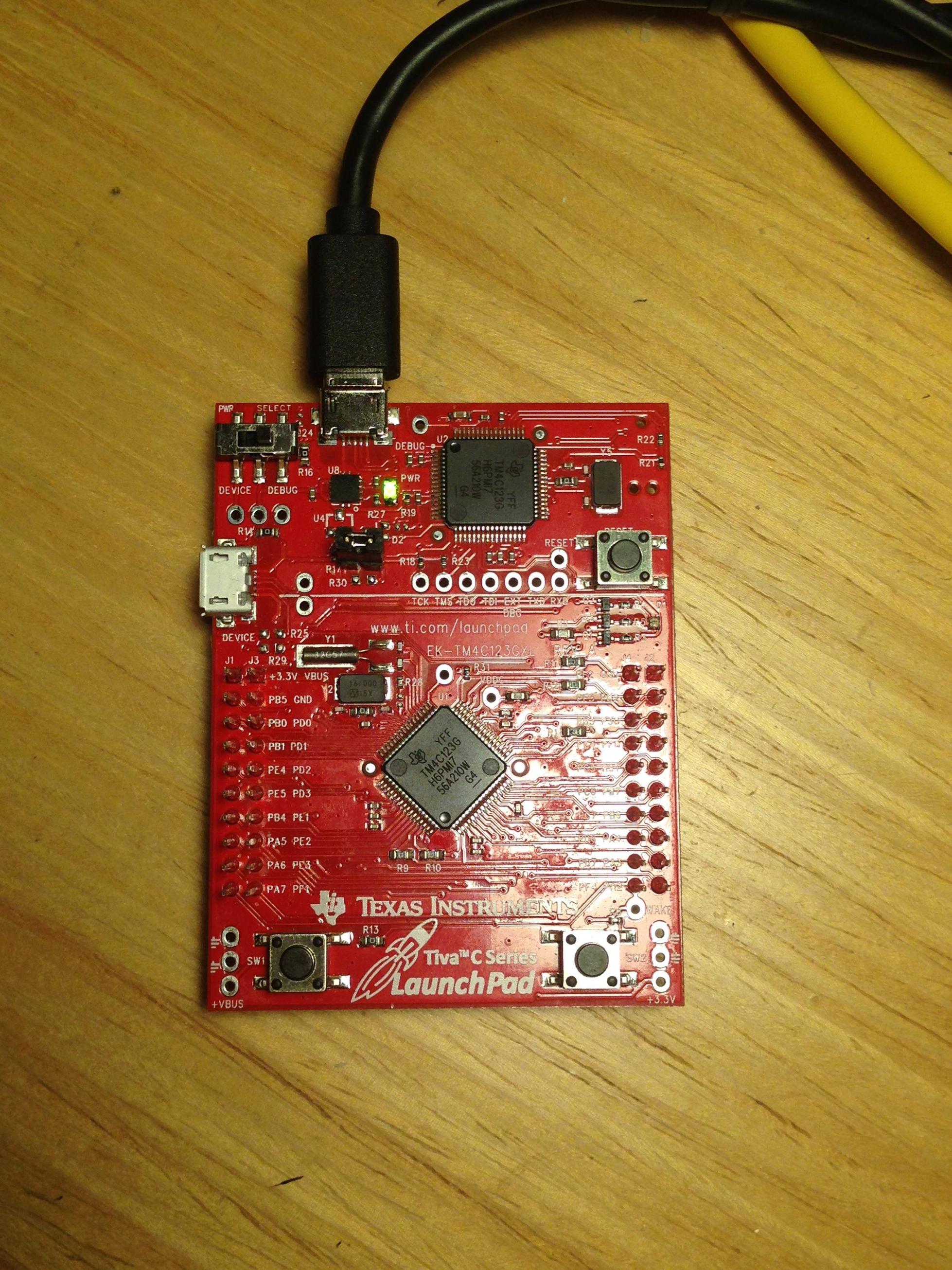
Now my LaunchPad is dead now, and this is exactly how it looks:

enter image description here

Let me describe it: A steady half-green-and-yellow light indicating the power on, and that's all. I strongly want you to know that I PLUGGED the LaunchPad in my computer and it did NOT CONNECT to the computer AT ALL:

  1. The computer didn't play the sound as usual when it detected USB connection.
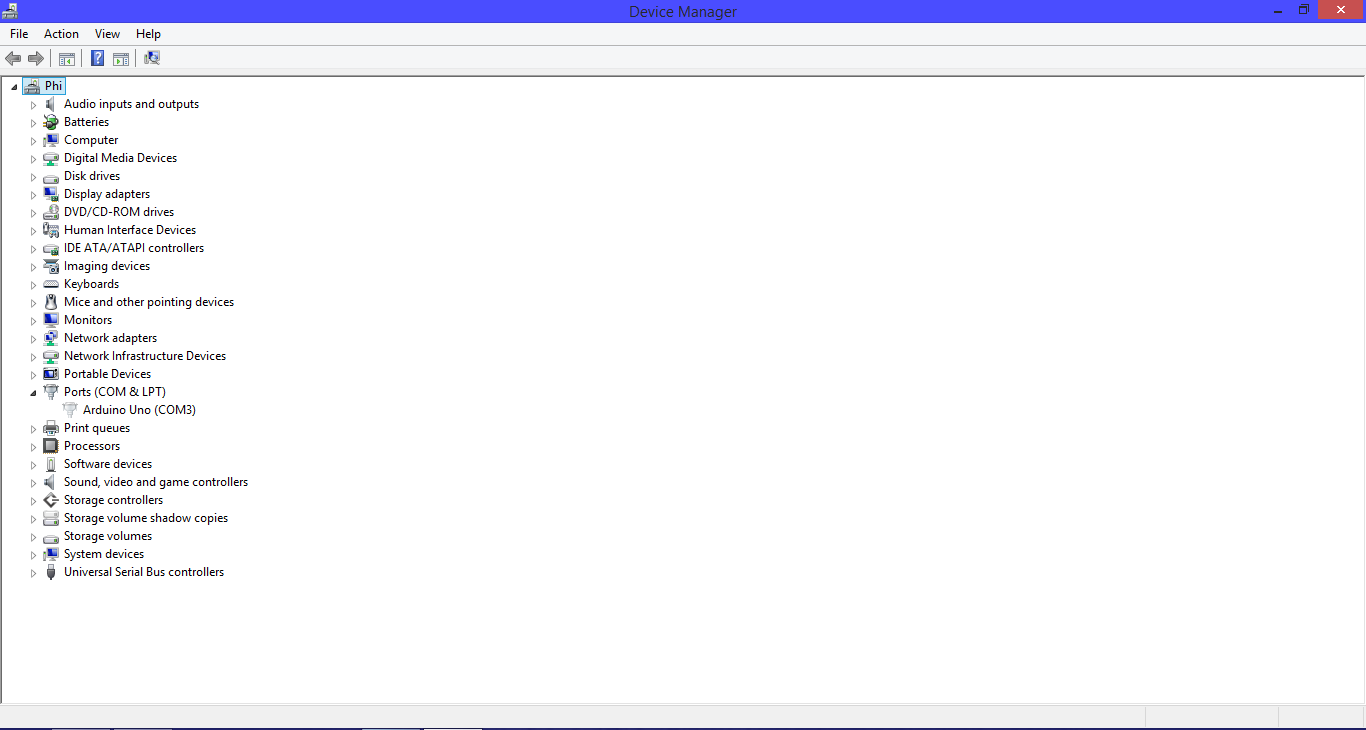
  2. There is no driver appeared in Device Manager although I had already viewed all hidden Devices:

enter image description here

There should be Stellaris Virtual COM Port located inside Ports, and there should be Stellaris In-Circuit Debug Interface (ICDI) driver as well. They disappeared, all of them.

  1. From 1 and 2, I'm pretty sure that there is no way to erase and reset the factory settings for the LaunchPad.
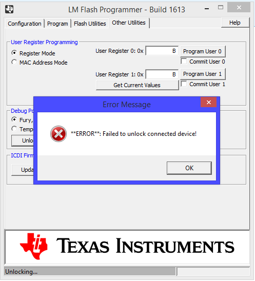
  2. I had already used LMFlashProgrammer from TI:

enter image description here

  1. I had already used other USB ports on my computer.
  2. I had already used other computers.
  3. I had already tried to press the Reset button, even SW1 and SW2, but nothing happened.
  4. Please don't tell me to upload the blink example (or any code) to the LaunchPad. I had told you, the computer didn't recognize the LaunchPad AT ALL.

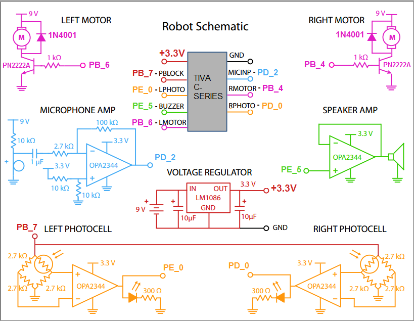
[Editted] My schematic:

enter image description here

IMAGINATIVELY, IT WAS LIKE I LEFT THE KEY IN THE ROOM AND LOCKED THE DOOR.

Please help me with this problem! I feel frustrating now, and I need the LaunchPad back. I'm in an online course and it is in session! SINCERELY THANKS!

\$\endgroup\$
9
  • 1
    \$\begingroup\$ R9 and R10 connect PD0&PB6 and PD1&PB&, respectively. Be aware that the jumpers must be desoldered and removed if you want to use either of these pairs of pins. I've heard that the board can be damaged if both of these are used as outputs simultaneously. \$\endgroup\$
    – Pigrew
    Commented Mar 15, 2016 at 7:52
  • 5
    \$\begingroup\$ @phil3c7r0n - To reduce the chances of other readers duplicating effort from your previous question about the same problem, here is a link to it for other people to read: electronics.stackexchange.com/questions/222331/… : Since your code mentions driving motors for a robot, there are ways you could have caused hardware damage to your LaunchPad board e.g. if there was insufficient reverse voltage clamping etc. - you didn't supply a schematic for readers to be able to consider that possibility. I suggest ordering a new board :-( Good luck \$\endgroup\$
    – SamGibson
    Commented Mar 15, 2016 at 12:01
  • 1
    \$\begingroup\$ Realistically you have two options. One involves a sacrifice, at midnight on the night of a full moon, in a forest clearing, the other involves $12.99 and the Texas Instrument website. I will not comment on the respective merits of either. \$\endgroup\$
    – user16324
    Commented Mar 15, 2016 at 12:35
  • 1
    \$\begingroup\$ Here is the data sheet, ti.com/lit/ds/symlink/tm4c123gh6pm.pdf it would be your best resource for resolving this issue. And here are the schematics ti.com/lit/ug/spmu296/spmu296.pdf Which shows the PB_4 and PB_6 are just GPIO on U1-A on Sheet 1 of the schematics. 4.3.4.3 in user manual has a reset procedure. And.... I have already wasted $12.99 of everyone's time. \$\endgroup\$
    – Tyler
    Commented Mar 16, 2016 at 0:51
  • 3
    \$\begingroup\$ Remember to desolder R9 and R10 before use, so that the I/O ports can be used independently (without damaging the board). \$\endgroup\$
    – Pigrew
    Commented Mar 17, 2016 at 0:51

1 Answer 1

1
\$\begingroup\$

I, too, once destroyed my Tiva C-series dev board. Maybe the high inductance of motors drew current even when the output stage of the uC pins tried to protect itself. I can't see what is wrong in the picture of the board you posted. You can spend hours debugging this, and perhaps someone knows exactly what you did. However, the board is $25 and ships next day from digikey.

\$\endgroup\$

Your Answer

By clicking “Post Your Answer”, you agree to our terms of service and acknowledge you have read our privacy policy.

Not the answer you're looking for? Browse other questions tagged or ask your own question.