0
\$\begingroup\$

I am trying to drive a "piezo atomizer" which is pretty much a transducer from what I can see.

The specs on the transducer are as follows:

-30-50VPP

-Resonant frequency fr: 190 KHz±5KHz

-Resonant impedance Zm: ≤250 Ω

-static capacitance Cs: 2.2nF ±30%

-Test Condition: 25±3 °C 40~70% R.H.

-Cs => LCR meter at 1KHz 1Vrms

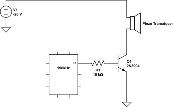
I thought I would be able to drive the transducer using the following circuit. I can get the the transducer to creak small bubbles when its in water but I can not get it to act like it should (a small humidifier).

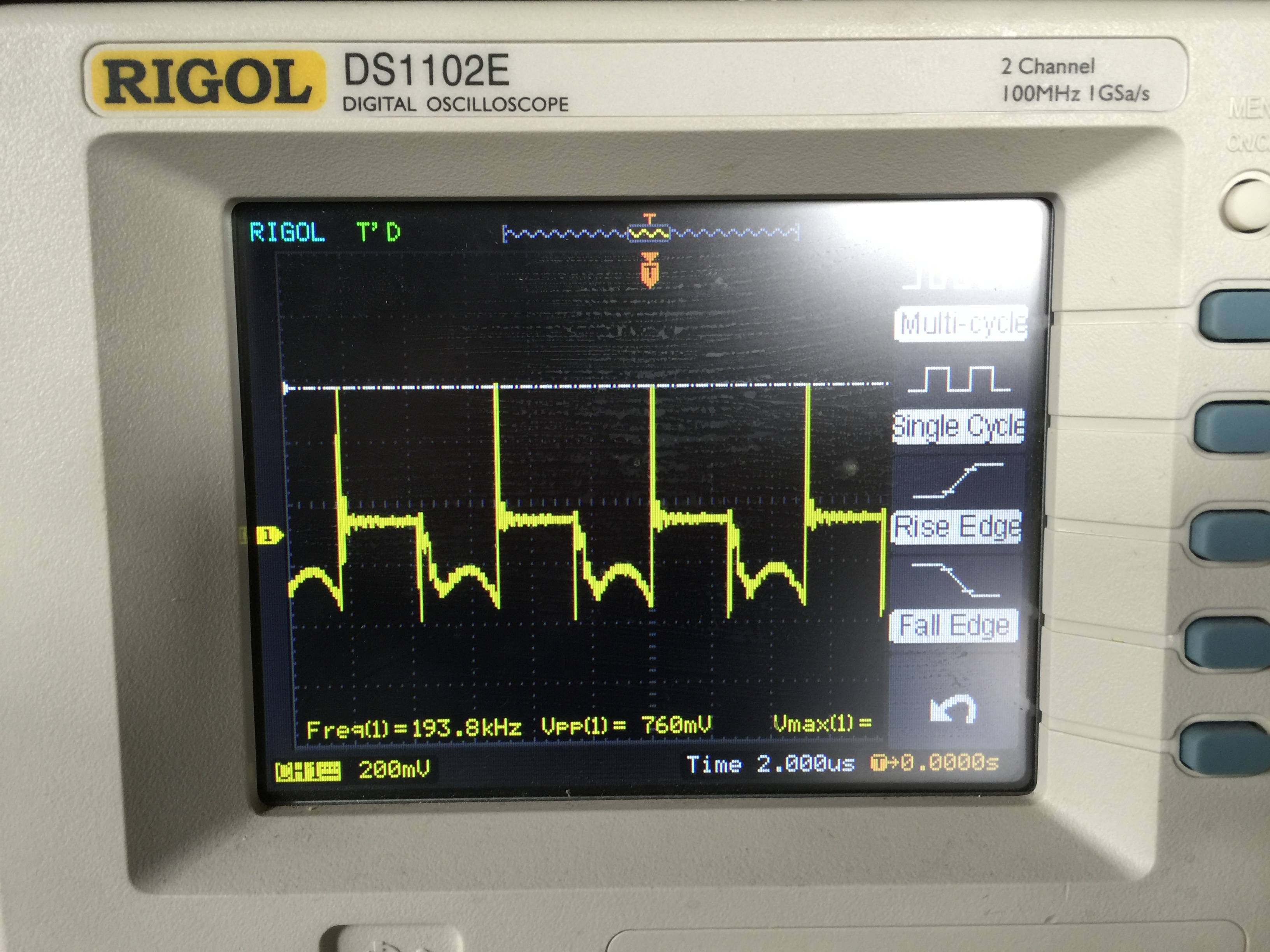
This is what I am getting from the net that connects collector of the npn and the negative lead of the piezo. enter image description here

Any suggestions as to where I am going wrong?

schematic

simulate this circuit – Schematic created using CircuitLab

\$\endgroup\$
8
  • \$\begingroup\$ What signal are you getting across the piezo? \$\endgroup\$
    – Andy aka
    Commented Apr 6, 2016 at 14:27
  • \$\begingroup\$ I updated the original question with a scope trace! \$\endgroup\$
    – mitch33
    Commented Apr 6, 2016 at 14:45
  • \$\begingroup\$ Is your supply actually a -20V source, as V1 shows? \$\endgroup\$
    – uint128_t
    Commented Apr 6, 2016 at 14:52
  • \$\begingroup\$ Im sorry that should be positive 20. I have varied it from the requested 30-50V with no luck \$\endgroup\$
    – mitch33
    Commented Apr 6, 2016 at 14:55
  • \$\begingroup\$ Am I mistaken that I can drive a piezo this way? \$\endgroup\$
    – mitch33
    Commented Apr 6, 2016 at 15:59

1 Answer 1

2
\$\begingroup\$

The piezo transducer is series resonant at 190 kHz. This is clear from the spec because it mentions that the resonant impedance is less than 250 ohm. Unfortunately you are driving it as if it is parallel resonant but this may not be specified by the supplier. Parallel resonance should occur somewhere quite close to the series resonant point so try adjusting the frequency until you hit a parallel resonant peak but do it carefully.

The care I suggest is to bias the transistor so that it always conducts some DC current - to do this you will need a resistor in parallel with the piezo device because on its own the piezo will not conduct DC and therefore the transistor will not operate correctly. Maybe try a 1 kohm to 10 kohm resistor in parallel.

Next drive a much smaller (maybe 50 mVp-p) signal into the base via a coupling capacitor so you don't upset the bias point set on the base. I'm attempting to convert your transistor stage into a class A amplifier - if you need help understanding that try googling for typical circuits.

Now with this set up you should be able to find the parallel resonant point and close by (when the signal collapses) you will find the series resonant point.

It may work in parallel resonant mode satisfactorily in which case you can try upping the driving voltage amplitude but, more likely is that you will need to operate it in series resonance to get the higher power you desire. Try googling for driver circuits and take note that there are a few ideas on driving piezo devices like this on stack exchange.

There are a few things that need to be put in place circuit wise when driving anything other than a few milli watts into a piezo - the resonant point is very, very sharp and a control loop may well be required to keep the driving frequency following the small changes in operating frequency of the piezo. There is also an amplitude control loop required and together these are not simple things to get right first time so do some research because it's beyond the scope of this site to go much deeper especially to a novice.
\$\endgroup\$
6
  • \$\begingroup\$ Thanks for the great response. That helps a lot. I was able to get it to slightly produce some mist. Can you explain a little more about finding the series resonant point? Am I changing the frequency to try and find it. And after I do find that point, Are you saying that I would go back to my original schematic and with that frequency it should work? Thanks for all of the help \$\endgroup\$
    – mitch33
    Commented Apr 7, 2016 at 15:20
  • \$\begingroup\$ I'm not sure what it is you want me to explain explicitly - I could rant on and fill several pages and still not hit the spot for what you specifically need to understand. Your original schematic doesn't work so why go back to it. It also won't work in series res mode either. \$\endgroup\$
    – Andy aka
    Commented Apr 7, 2016 at 16:39
  • \$\begingroup\$ Thanks for the response I did quite a lot of research and ended purchasing another transducer with a 12V DC supply at 117 +- 3kHz frequency and was able to find the resonate point and get it working relatively well. \$\endgroup\$
    – mitch33
    Commented Apr 18, 2016 at 14:07
  • \$\begingroup\$ Are you saying you gave up on AC driving that original device because there is one that has an inbuilt amplifier and runs from DC? \$\endgroup\$
    – Andy aka
    Commented Apr 18, 2016 at 14:17
  • \$\begingroup\$ Not quite. Actually I am a bit confused on how but the specs for this transducer just say 12V DC. steminc.com/PZT/en/piezo-atomizer-120-khz-7um Using the technique that you described I am able to get the device producing mist but at a much lower voltage - 6-7 VPP \$\endgroup\$
    – mitch33
    Commented Apr 18, 2016 at 14:54

Your Answer

By clicking “Post Your Answer”, you agree to our terms of service and acknowledge you have read our privacy policy.

Not the answer you're looking for? Browse other questions tagged or ask your own question.