0
\$\begingroup\$

I want to make a DTMF decoder and use it on an internal DC phone line. I made a decoder with PIC microprocessor (Black DTMF decoder) that works with signals around 0V. My internal phone line consists of a 9V battery, a 330 ohm resister and a phone, all in a series circuit and the DTMF signal is read from resistor ends. My problem is that the signal is always above 0V (around 3.5V that changes if I use another phone) and I need to shift it around 0V but I don't know how?

Edited: This is my circuits diagram.
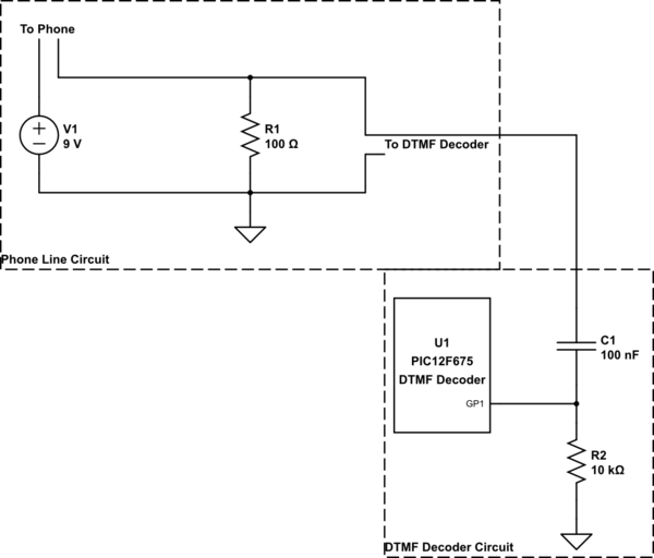
schematic

simulate this circuit – Schematic created using CircuitLab

\$\endgroup\$

1 Answer 1

2
\$\begingroup\$

schematic

simulate this circuit – Schematic created using CircuitLab

Figure 1. Decoupling capacitor for DTMF signal.

You need to decouple the DTMF signal with a series capacitor. It will block the DC component from reaching the DTMF decoder.

Unfortunately you haven't given a circuit schematic of your setup or any component values so I can't be any more specific.

\$\endgroup\$
3
  • \$\begingroup\$ I added the circuit diagram. \$\endgroup\$
    – Vahid
    Commented Apr 7, 2016 at 9:20
  • \$\begingroup\$ So is there still a question? \$\endgroup\$
    – Transistor
    Commented Apr 7, 2016 at 21:25
  • \$\begingroup\$ Oh, there was a problem with pin direction register. It is now working. \$\endgroup\$
    – Vahid
    Commented Apr 8, 2016 at 12:17

Your Answer

By clicking “Post Your Answer”, you agree to our terms of service and acknowledge you have read our privacy policy.

Not the answer you're looking for? Browse other questions tagged or ask your own question.