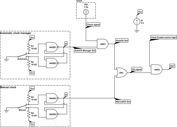
I'm building an 8 bit computer and I've just developed the clock.
I used a NE555 (datasheet) with some other integrated (74 series) to manage it.
- The operator could stop signal from 555 (with a switch) and use it in "manual mode" using another switch.
- No clock signal should reach the output pin if clock enable pin is low.
To achieve this I useed:
- 74HC00 (NAND) to debounce manual switch
- 74HC00, 74HC08 (AND) to debounce auto witch and signal from 555
- 74LS32 (OR) to get the manual clock or the automatic clock (with 555)
- 74HC08 to get an high value on the output pin if both clock and clock enable are high.
I hope this diagram will be more clear than my words:

simulate this circuit – Schematic created using CircuitLab
Now I'm testing it and what I got is really strange!
First I tested it with a 74HC161 (datasheet), a synchronous 4-bit counter: what I got is ok: I see
0000,0001,0010, ...,1111as expected.Then I used a 74HC4017 (datasheet), a 10-bit ring counter with the clock inverted by a 74LS04 as it need to be in my computer:
Unexpectedly at "high" frequencies (2Hz), using the automatic mode, the counter becomes active with bot high-to-low and low-to-high tranistion. Using the manual this behavior never occurs.
Than if I switch off the automatic clock manager and put clock enable to ground the counter continue advancing the high bit. Note: manual clock is low.
On the other hand if I switch off 555 and I use only manual clock the integrated word fine.
So I checked the voltage value between OUT and ground and what I got is 0.07 V . It's a too small amount to be evaluated by the 744017, but it seems to evaluate it anyway.
How to repair my circuit? What is wrong with it?
Any idea/solution/hint will be appreciated.
