1
\$\begingroup\$

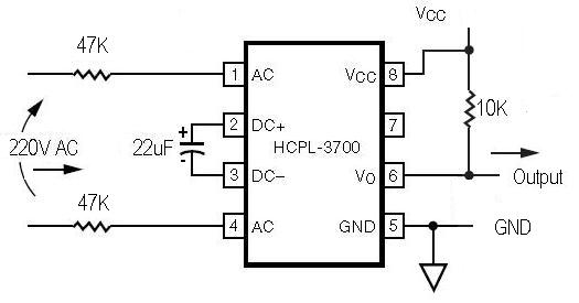
Looking for some clarification on the proper wiring of an AC/DC optocoupler (HCPL3700, datasheet) when working with 120vac.

enter image description here

From what i read online it looks like a need a resistor on the hot side and a capacitor across the DC inputs. Most of the diagrams i see online specify a 47k ohm resistor on both the hot and neutral side, per the datasheet if i'm reading it right the opto can only handle about 5v on the AC input, but i don't believe that a 47k ohm resistor will drop 120vac to 5vac, it should only drop to 60vac of both resistors are the same. So my question is am i reading the datasheet wrong or am i interpreting the circuit examples i see incorrectly?

\$\endgroup\$
9
  • \$\begingroup\$ Have you looked at Fig 8 in the Fairchild datasheet? \$\endgroup\$
    – Tyler
    Commented Apr 12, 2016 at 23:30
  • \$\begingroup\$ Please include an example of "the diagrams I see online", so we know what you're talking about. If you don't have enough rep to a add an image, provide a link and someone will turn it into an image for you. \$\endgroup\$
    – The Photon
    Commented Apr 12, 2016 at 23:33
  • \$\begingroup\$ i see the diagram but im not clear as to what V+/- are, is that referring to the hot and neutral side of the AC input? \$\endgroup\$ Commented Apr 13, 2016 at 0:02
  • \$\begingroup\$ I don't see any "V+" or "V-" in your diagram. \$\endgroup\$
    – The Photon
    Commented Apr 13, 2016 at 2:04
  • \$\begingroup\$ sorry, that response was for @Tyler in regards to Fig 8 in the datasheet. \$\endgroup\$ Commented Apr 13, 2016 at 12:37

2 Answers 2

2
\$\begingroup\$

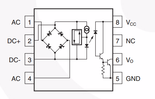
The Fairchild datasheet for your part shows some more details of what's going on inside:

enter image description here

You can see that the 47 kOhm resistors on the AC pins are mainly limiting the current being delivered to the diode bridge. Exactly what voltage is seen by the internal circuits connected to the diode bridge depends on the I-V characteristics of those devices.

\$\endgroup\$
3
  • 1
    \$\begingroup\$ But since those 2 resistors are the same wouldn't that just create a current divider and drop the 220V to 110V? And to that point is there anywhere in the datasheet that specifies the max voltage that can be applied to the AC pins? \$\endgroup\$ Commented Apr 13, 2016 at 12:41
  • 1
    \$\begingroup\$ Most 1/4 W resistors aren't rated for 230 V AC. For this reason the required resistance is split into two series-connected resistors of half the required value. Putting one on each input makes the circuit look pretty. \$\endgroup\$
    – Transistor
    Commented Apr 13, 2016 at 14:31
  • 1
    \$\begingroup\$ ok, i see the mistake i made, i thought they were trying to reduce the voltage to the AC side with a voltage divider, but they are using the resistors in series, if i use the Input threshold current from the datasheet that would explain the resistors. So i suppose voltage doesnt play a part in this application, to an extent? Anyway can anyone commend on the proper wiring of the DC side? im only familiar with optos with 1 transistor inside whereas this one appears to have 2. \$\endgroup\$ Commented Apr 13, 2016 at 21:00
0
\$\begingroup\$

I finally got a stable circuit after carefully reading the datasheet and some trial and error, 47k resistor on one of the legs (this is 120vac), .01uf cap from pin 8-5, 10uf cap from pin 6-5, 10k resistor from pin 8-6, pin 8 to ground. pin 6 is output. what i didnt realize about this otpo is that when the AC side is high the opposite side of the opto is low, current flows through the internal resistor to ground not through the 10k to pin 6. when the AC side is low the current flows through the 10k resistor making pin 6 high. in my case i fed pin 5 with 5vdc. Thank you everyone for you help.

\$\endgroup\$
4
  • \$\begingroup\$ Pin 7 is NC! The internal resistor does not matter (it has current flow only when the transistors are on anyway). When the transistors are off, nothing flows through the 10k resistor. \$\endgroup\$
    – CL.
    Commented Apr 14, 2016 at 6:59
  • \$\begingroup\$ sorry, i updated the answer, i mistyped the pins. when the transistors are off is the only time i get power through the 10k, per the datasheet when the transistors are on the output pin should be low. \$\endgroup\$ Commented Apr 14, 2016 at 14:03
  • \$\begingroup\$ What does "pin 8 to ground" mean? (All these mistakes are why you should draw a schematic.) \$\endgroup\$
    – CL.
    Commented Apr 14, 2016 at 14:25
  • \$\begingroup\$ i connect pin 8 to ground, not sure how else to explain that. This recent mistake was because mistyped the pin numbers, the other confusion i have was in the operation of the opto itself. I use fritzing for my schematics. \$\endgroup\$ Commented Apr 14, 2016 at 21:03

Your Answer

By clicking “Post Your Answer”, you agree to our terms of service and acknowledge you have read our privacy policy.

Not the answer you're looking for? Browse other questions tagged or ask your own question.