1
\$\begingroup\$

I am currently testing a 50MHz 3.3V CMOS oscillator in my circuit, which is connected to two pins/loads - MCU pin and Ethernet PHY pin. The oscillator is rated for 15pF output load, which I could be exceeding by a few pF perhaps. Things are working fine in my circuit and so is the Ethernet Communication.

Now, the oscillator Vcc is supplied by 3.3V. When I am observing the waveform at the output pin of the oscillator, I am getting a 4V high, 0.8V low 50MHz sine waveform. I am wondering what is causing the voltage to go to 4V when my supply vltage is 3.3V? I have a 10R resistor at the oscillator output which is provided for termination adjustment.

Note: I am testing the waveform using an oscilloscope of 100MHz bandwidth, because I don't have any other oscilloscope at hand. But I think that should actually result in lesser amplitude.

Diagram:
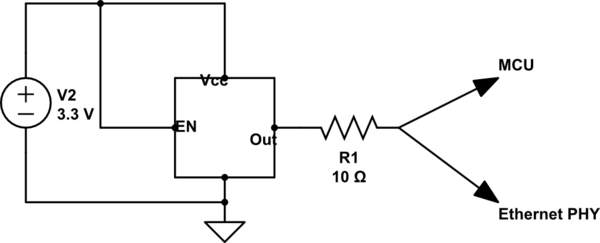
schematic

simulate this circuit – Schematic created using CircuitLab

Could anyone please help me in identifying the reasons for this higher output voltage?

Let me know if I missed providing any important information required for the analysis.

Thank you.

EDIT: The higher voltage is irrespective of Ethernet cable connection.

\$\endgroup\$
8
  • \$\begingroup\$ There's a circuit diagram editor that you can use to insert a schematic. Edit your question and press CTRL M to open the schematic editor. \$\endgroup\$
    – JRE
    Commented Apr 13, 2016 at 11:25
  • 1
    \$\begingroup\$ Check your scope probe calibration! Use the calibration output and adjust probe for maximum flatness, then re-measure... \$\endgroup\$
    – user16324
    Commented Apr 13, 2016 at 11:27
  • \$\begingroup\$ When something doesn't go up to expectations, often the expectations just have to be adjusted. If the real question is "Why do I expect the wrong thing" then a schematic alongside with your calculations and explanation about why you expect it are the only way to point out errors in your reasoning \$\endgroup\$
    – PlasmaHH
    Commented Apr 13, 2016 at 11:33
  • \$\begingroup\$ Is your 'scope's ground reference connected near the oscillator or far away? \$\endgroup\$
    – brhans
    Commented Apr 13, 2016 at 11:37
  • \$\begingroup\$ I have included the schematic; sorry for the not so good one. \$\endgroup\$
    – LoveEnigma
    Commented Apr 13, 2016 at 11:46

3 Answers 3

1
\$\begingroup\$

A pure square wave of amplitude 3.3 volts p-p when perfectly filtered to remove its harmonics will result in a sinewave whose amplitude is 27% higher at 4.2 volts p-p: -

enter image description here

Notice that the fundamental is higher amplitude than the perfect square wave. If you do the math you'll find that the fundamental is \$\dfrac{4}{\pi}\$ times higher that the square wave.

Somewhere between perfect filtering and the filtering provided by your o-scope you get what you get.

\$\endgroup\$
5
  • \$\begingroup\$ Thank you for the answer, really helpful. So, does it mean that the only reason for this higher voltage is the limited bandwidth of my oscilloscope (100MHz)? If so, the waveform should look closer to a square wave if I measure with a high bandwidth oscilloscope, right? One more question: When I am reducing the ground lead length, the amplitude of the sine waveform is reducing to ~3.6V, which is understandable, but I am wondering whether the ground lead length and signal reflection are also contributing in the ~4V measurement? Any comments on this? Thanks. \$\endgroup\$
    – LoveEnigma
    Commented Apr 14, 2016 at 4:27
  • \$\begingroup\$ Wider bandwidth scope = better looking square wave. 50 MHz has a wavelength of about 4.5 metres. The 3rd harmonic will be 1.5m and fifth harmonic 0.9m so you can expect some nuances affecting the higher order harmonics but remember these contribute less to the shape than the fundamental and 3rd. \$\endgroup\$
    – Andy aka
    Commented Apr 14, 2016 at 7:19
  • \$\begingroup\$ Thanks. That's right, but I just measured the waveform again with probe tip ground tip suggested above and I could get a really good waveform of 3.3V. Of course, it wasn't a perfect square wave, as that is limited by my oscilloscope BW. As scope is of 100MHz BW, I am mostly seeing the fundamental only, which is decent. The main thing to note was that the voltage now was just what I expected; 3.3V and not 4V. To conclude - Does this mean that the 4V problem was only due to improper probe grounding AND the not-so-squarish shape only because of less oscilloscope BW? \$\endgroup\$
    – LoveEnigma
    Commented Apr 14, 2016 at 9:56
  • 1
    \$\begingroup\$ From a million miles away it's a guess. \$\endgroup\$
    – Andy aka
    Commented Apr 14, 2016 at 10:38
  • \$\begingroup\$ Haha, alright. Thank you again for your help from a million miles. :) \$\endgroup\$
    – LoveEnigma
    Commented Apr 15, 2016 at 4:41
1
\$\begingroup\$

Your scope has insufficient bandwidth for such measurements. The square or almost square wave (that your CMOS oscillator makes) has amplitude of the first harmonic higher than the amplitude of square signal. Your scope filters out the next (third) harmonic and all higher ones. So you see more volts than you expect.

Guess your circuit works fine, no need to change it :)

\$\endgroup\$
1
  • \$\begingroup\$ Thank you for the answer. Yes, that's right. I will try to see if I can measure with a higher bandwidth oscilloscope. Yes, I will leave it as circuit works fine, but just want to analyze this a bit for better understanding. :) \$\endgroup\$
    – LoveEnigma
    Commented Apr 14, 2016 at 4:29
1
\$\begingroup\$

If the connecting wires are long, when pulse risetime are fast, more than few inches, they behave as transmission lines and could reflect back some energy increasing, due to resonance effect, the voltage at the transmitting end. This could also damage the line driver device, so it is important to terminate with the right impedance the wires, generally around 50 to 75 ohm are good. Obviously the reflected waveform is generally sinusoidal near the resonant frequency of the line.

\$\endgroup\$
1
  • \$\begingroup\$ Thank you for the answer. Yes, it is logical that reflection could also be one of the reasons, but the reason I only had 10R when designing is because I am driving two loads with the same oscillator output and was worried about the voltage drop in the oscillator output with higher termination resistance of ~50R. I can't the design at the stage I am in now, but I will change the resistor and see the waveform again. There are three things at play here: oscilloscope bandwidth, ground lead length, and signal reflection. Will try to verify each of them individually and together. \$\endgroup\$
    – LoveEnigma
    Commented Apr 14, 2016 at 4:32

Your Answer

By clicking “Post Your Answer”, you agree to our terms of service and acknowledge you have read our privacy policy.

Not the answer you're looking for? Browse other questions tagged or ask your own question.