3
\$\begingroup\$

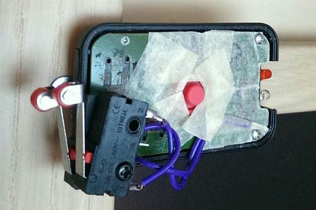
I want my sliding door to turn off the tv. So I opened the remote control of the TV, soldered a KW12-3 switch to the pads of the original ON/OFF momentary button, and everything is working good, I press the switch once and it turns off, and the same for turning the TV on. The problem is, when I tape my "creation" to the sliding door and the door is closed, my switch is always pressed, and the remote is constantly turning off and on the tv.

So I would need a switch which, after closing the circuit, even if not released, will open it again. Do I need a different kind of switch or I actually need to add other components such a capacitors and inductors? I'm sorry for my total ignorance about the subject, but I hope I explained the problem well.

enter image description here

The remote control and trigger switch I'm working on.

I actually bought the small universal remote and soldered the switch to it from the other side of the pcb. The tape is there just to blend with the color of the door, and to hold the red push button which is used to program the remote. The whole thing is about 4cm on the longest side, totally invisible if I tape it on top of the door, so I would be happy if it will work as I intend.

\$\endgroup\$
5
  • \$\begingroup\$ Your link gives error "The client and server don't support a common SSL protocol version or cipher suite. This is likely to be caused when the server needs RC4, which is no longer considered secure." on Google Chrome. \$\endgroup\$
    – Transistor
    Commented Apr 19, 2016 at 17:36
  • \$\begingroup\$ You probably could use your current switch and a "single shot" reset circuit. It'll just make a spike every time the switch is pushed, even if it not released. \$\endgroup\$
    – b degnan
    Commented Apr 19, 2016 at 17:45
  • \$\begingroup\$ I know you mean this as a serious question, but when I read the question, my first thought was media1.giphy.com/media/Eb4HAUeQrq608/200.gif \$\endgroup\$
    – Cort Ammon
    Commented Apr 20, 2016 at 0:29
  • \$\begingroup\$ See electronics.stackexchange.com/questions/180716/… \$\endgroup\$
    – Passerby
    Commented Apr 20, 2016 at 0:49
  • \$\begingroup\$ Move the wire from the normally open (NO) contact to the normally closed (NC) contact. Now the switch opens when the door is closed. The TV will cycle on and off constantly when the door is open. Doesn't solve the problem, but makes it less crazy. And you learned something about switches. \$\endgroup\$
    – gbarry
    Commented Apr 20, 2016 at 1:36

2 Answers 2

3
\$\begingroup\$

One option is to use a magnet (on the door) and reed switch (on the frame) and mount the reed switch slightly back from the fully open position. In normal use the reed will pulse just before the door is fully opened and will turn off when actually fully open. You will still have the original problem if the door is stopped on the reed switch.

Depending on the orientation of the switch in your photo, you may be able to design a bump-cam to press the switch as it passes.

NO / NC switch combination

schematic

simulate this circuit – Schematic created using CircuitLab

Figure 1. Combination of two microswitches to give momentary pulse as door opens or closes.

A third option is to use a pair of the type of micro-switches you have already used.

  • Wire the switches in series as an NO and NC pair. (I've shown single-throw switches for clarity. You will use the appropriate contacts of the changeover micro switches.)
  • Bend the SW1 roller out so that it makes a little before SW2 breaks.
  • You should hear a double-click as the door is opened.

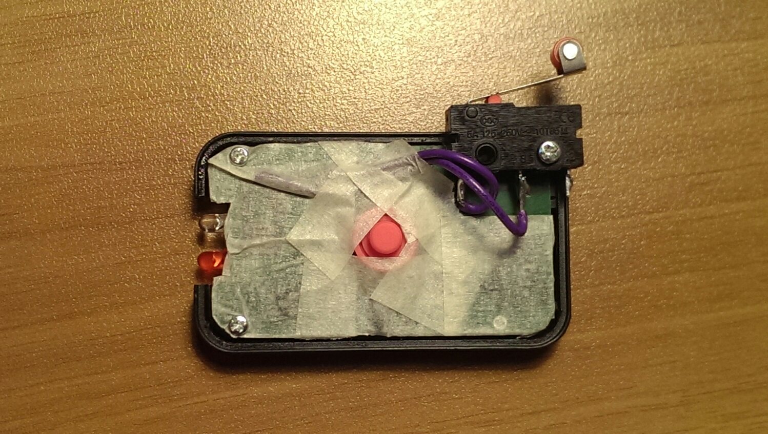
enter image description here

Figure 2. @Andrea's (the OP) implementation of the idea. Switches appear to be rotated to effect the make-before-break sequence rather than bend the lever as I suggested. Hi-res image here.

\$\endgroup\$
6
  • \$\begingroup\$ This is a nice idea, thanks! The only problem is I don't have a way to hide the magnet in the current situation, so other solutions are welcome. \$\endgroup\$
    – Andrea
    Commented Apr 19, 2016 at 17:48
  • \$\begingroup\$ Added second paragraph. (I also embedded the photo in your post.) \$\endgroup\$
    – Transistor
    Commented Apr 19, 2016 at 17:53
  • \$\begingroup\$ I'm probably going to order some reed switches then to try them out, I've found some Y213, are these good for this application? I can then put the magnet at any position I'd like and when the door slides over it it will both turn off the tv if it's on and turn it on if it's off. Am I correct? \$\endgroup\$
    – Andrea
    Commented Apr 19, 2016 at 19:07
  • \$\begingroup\$ You didn't provide a link to the Y213 so I don't know what it is but your understanding sounds correct. If added a third option which may suit you. See update. \$\endgroup\$
    – Transistor
    Commented Apr 19, 2016 at 23:42
  • \$\begingroup\$ Sorry about the link, I wasn't sure if I was allowed to post shops links. About the 3rd option that's clever! I am going to try it for sure tomorrow, also I'm probably going to order another remote and a reed switch just for experimenting. \$\endgroup\$
    – Andrea
    Commented Apr 20, 2016 at 22:56
0
\$\begingroup\$

It would be simple to just use a capacitor in series with the switch. When the switch is closed, current would flow while the capacitor is being charged-up, and then current would stop.

The tricky part is to figure out the value of capacitor since we don't know either the voltage or current required to trigger your remote control. And a secondary potential problem would be how to discharge the capacitor to reset it for another trigger.

In the 21st century, we can solve anything with a micro-controller (Arduino, et.al.) but that seems like shooting a fly with a canon.

\$\endgroup\$
3
  • \$\begingroup\$ I totally agree about the arduino, I didn't want to go that route because it's pretty much overkill. BTW the remote is powered by a CR2025 battery, so a 3v button battery. I don't know anything else, and even if I'm probably going to buy a magnetic switch I'm also gonna buy another remote and try both solutions, as with capacitors I will probably already have the necessary parts and not need to wait. If you can help me figure it out with capacitors it would be awesome. \$\endgroup\$
    – Andrea
    Commented Apr 19, 2016 at 20:59
  • \$\begingroup\$ @andrea you don't need a full 30 dollar arduino. A under one dollar ATTINY (with arduino firmware or not) or MSP430 or small microcontroller is all you need. An analog solution will be bigger, and probably take more power. Heck, you can even directly use an IR led, so you wouldn't even need the remote control. \$\endgroup\$
    – Passerby
    Commented Apr 20, 2016 at 0:48
  • \$\begingroup\$ "It would be simple to just use a capacitor in series with the switch." That depends on whether it's on a multiplexed circuit (scanning rows and columns) or not. The controller seems to have only one button so it may be a simple pull down or pull up but simply putting a capacitor in series is still pretty optimistic. \$\endgroup\$
    – Transistor
    Commented Apr 21, 2016 at 17:27

Your Answer

By clicking “Post Your Answer”, you agree to our terms of service and acknowledge you have read our privacy policy.

Not the answer you're looking for? Browse other questions tagged or ask your own question.