4
\$\begingroup\$

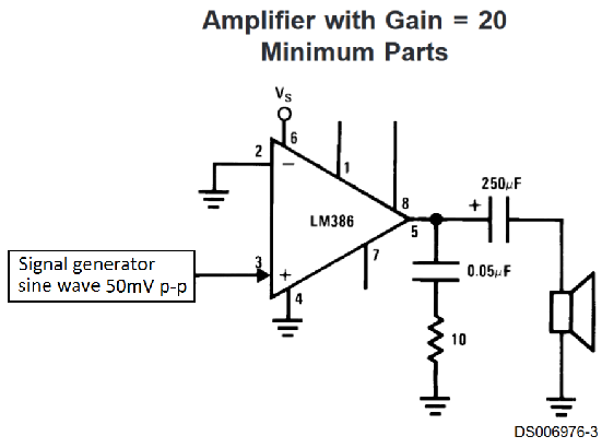
I recently made a circuit to test out LM386 audio amplifier for the first time on solderless board. I relied on the datasheet circuit shown below:

enter image description here

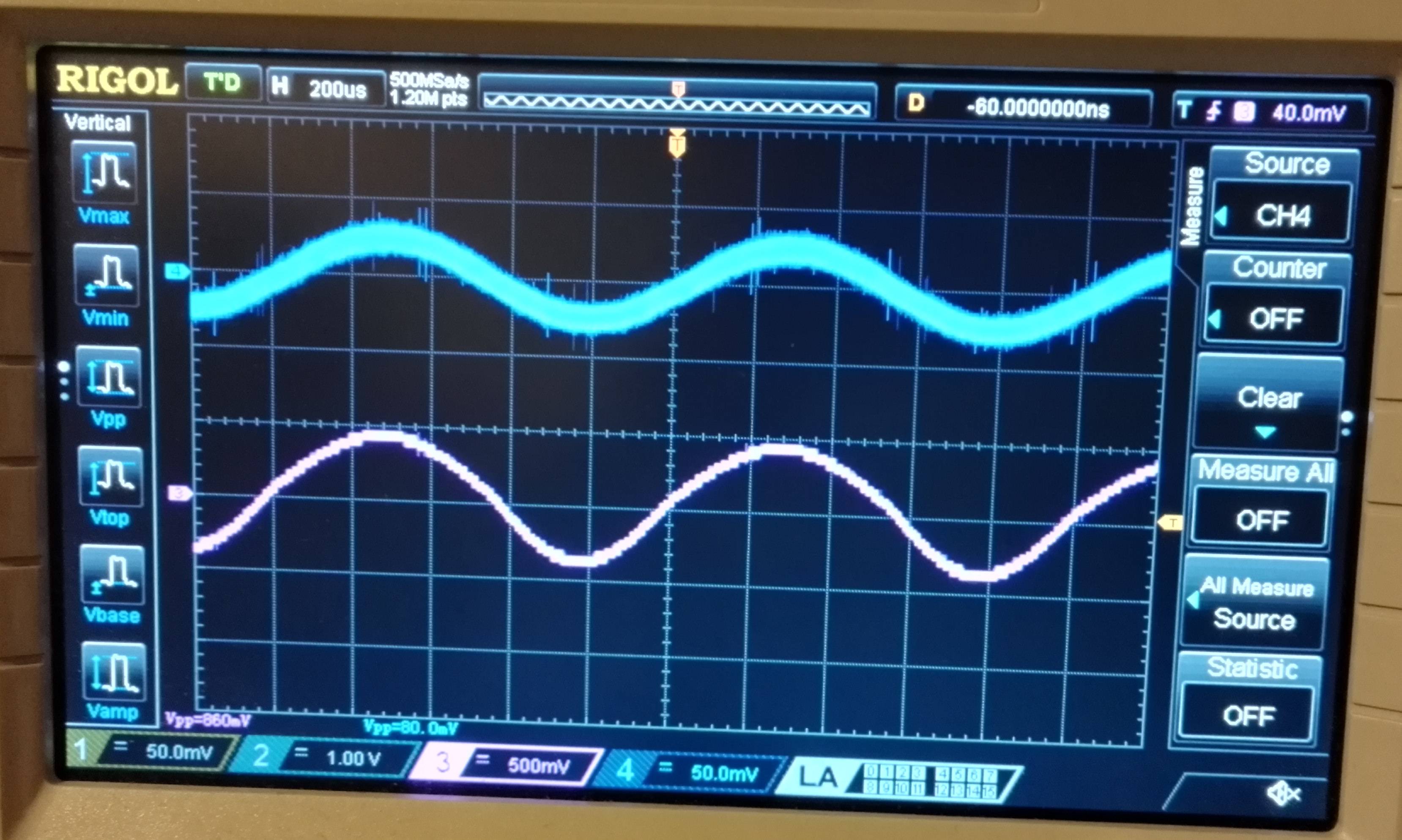
First I connected a 7.5ohm resistor at the output instead of a speaker. I get a clean sine wave at the output. The upper wave is the input while the lower wave is the output.

enter image description here

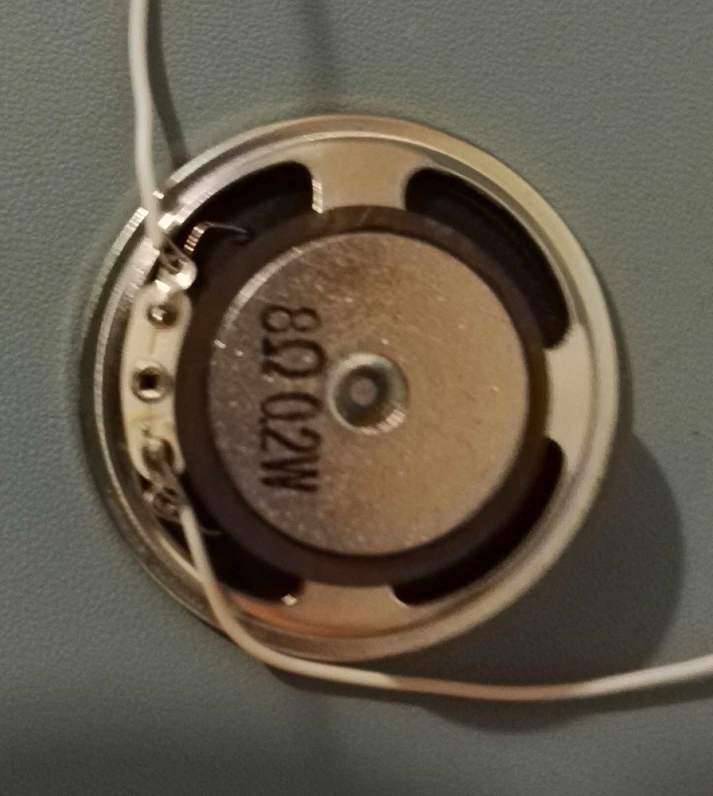
However, when I replace it with this speaker,

enter image description here

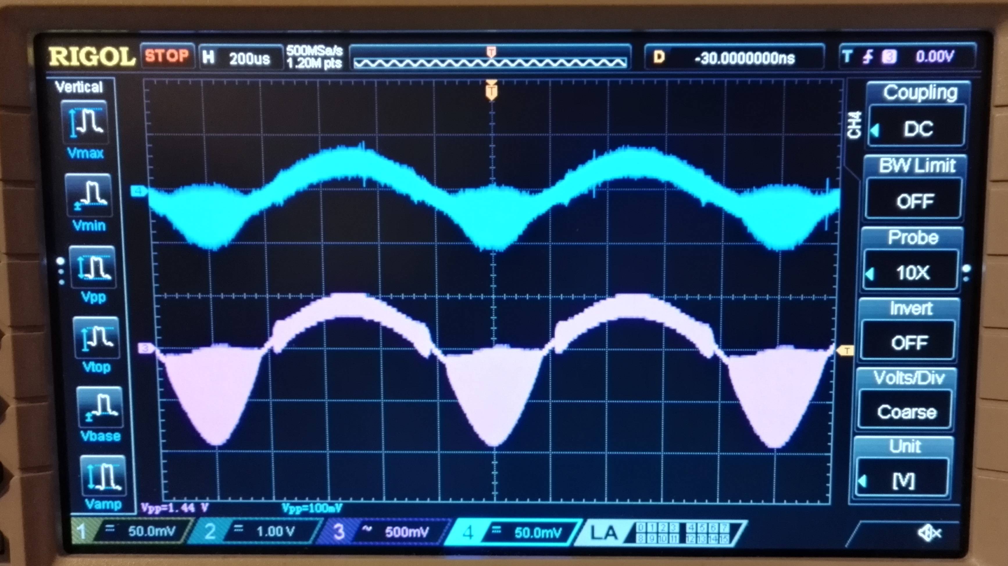
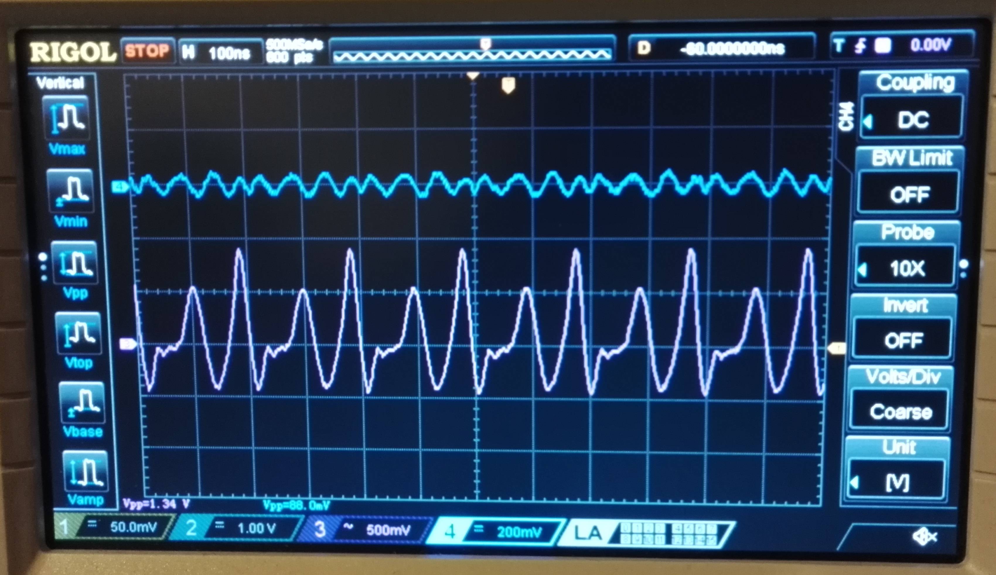
the output (and input) seems to become corrupted. Here is the scopeshot:

enter image description here

(1) Why could this be happening?

Besides this I am trying to figure out a few more things.

(2) Why do we have the output connected to ground via a 0.05uF capacitor and a 10ohm resistor in most schematics in the datasheet? What purpose does this serve since this is clearly not a filter.

(3) This is clearly a single supply amplifier topology. However, even if I provide it with a 100mV p-p signal, the negative cycle still shows at the output. How come???

(4) Why is output always capacatively coupled to a speaker? Is it because the DC signal may overheat the speaker?

(5) The bypass pin is used to prevent signal degradation as per the data? It says this pin may grounded or a capacitor used. How do I know which one I should do?

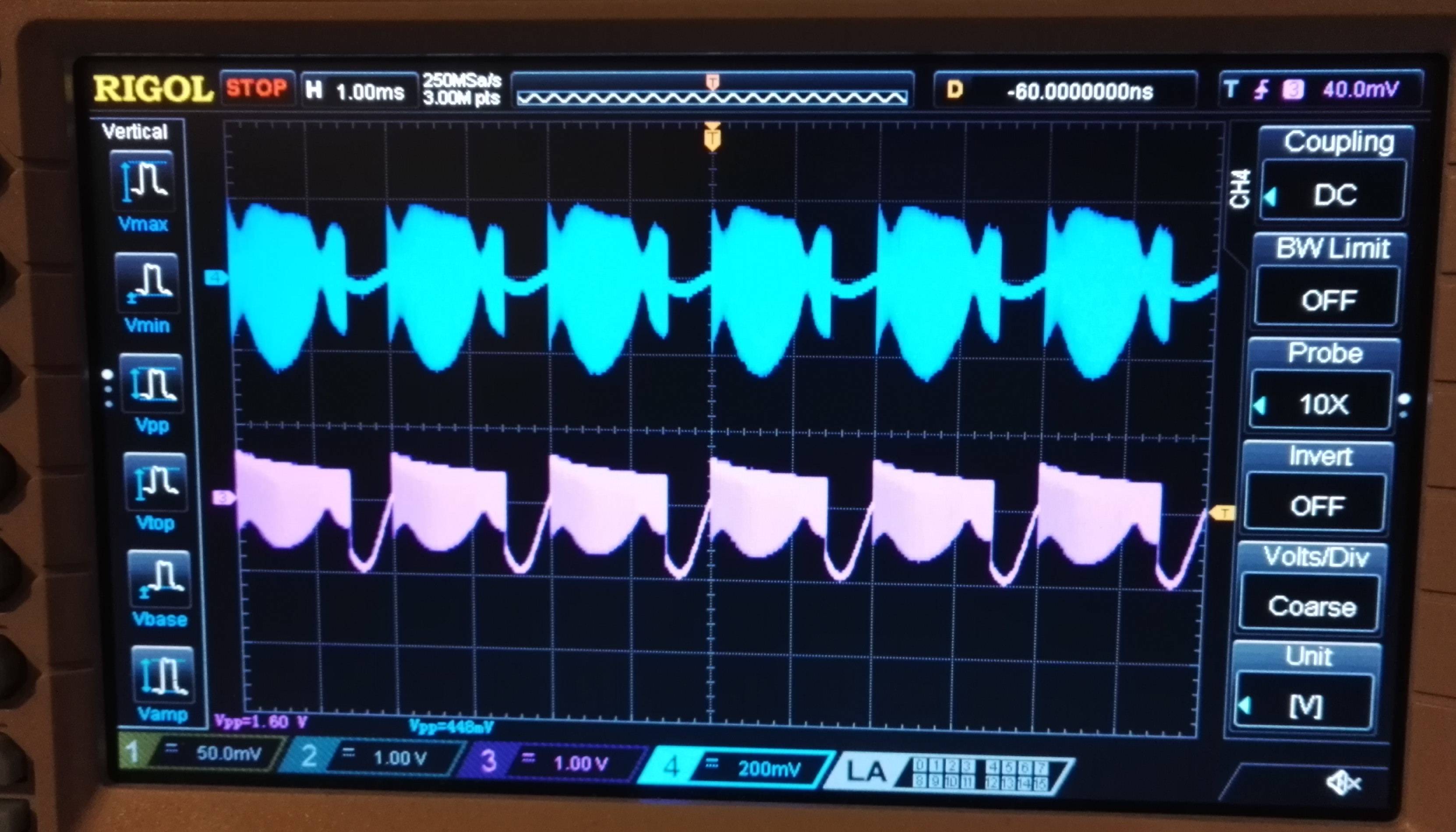
Finally, I made another interesting observation. Initially the output was completely corrupted, it was looking like this:

enter image description here

Then I realized that oh there is noise on the supply rails. When I added a 0.1uF capacitor, the noise went away and the amplifier output became a sine wave (when driving a 7.5ohm resistor). The noise looks like this:

enter image description here

I used AC coupling to be able to look at the noise. (6) Why does the supply noise above cause the amplifier to completely fail? Somehow without the smoothing capacitor, both input and output become corrupted.

\$\endgroup\$
4
  • \$\begingroup\$ I do not understand why the image expands to full size in the question area. Please let me know if it is possible to make it smaller. \$\endgroup\$
    – quantum231
    Commented Apr 24, 2016 at 19:35
  • 1
    \$\begingroup\$ For image sizing add an 'm' (medium) or 's' (small) before the '.jpg' file extension. \$\endgroup\$
    – Transistor
    Commented Apr 24, 2016 at 19:39
  • 1
    \$\begingroup\$ Ground loop wiring is your main problem - you can see it has also affected your input signal and even on the resistor load scenario the input signal is full of fuzziness; a sure sign of bad layout and power rails (+V and 0V) routed too close to input connections. \$\endgroup\$
    – Andy aka
    Commented Apr 24, 2016 at 19:49
  • \$\begingroup\$ Dear Andy, on the solderless board the power rails are on the top, then I am using jumper wires to connect the rails to the LM386 and other components. \$\endgroup\$
    – quantum231
    Commented Apr 24, 2016 at 20:36

4 Answers 4

4
\$\begingroup\$

I will answer your questions in the order that you asked them.

1) First you need to make sure you have a 470uF to 1,000uF capacitor from the power pin to ground pin. That will get rid of the 'self-oscillation' effect.

2) The .05uF and 10 ohm resistor on the output act as a phase-shifter, to cancel out the internal phase shifting caused by the LM386's own design. It is common to see this on many IC amplifiers.

3) The capacitor in series with the output not only blocks any DC voltage from going through the speaker, it effectively creates a new 'AC' based signal, with no DC component.

4) Because there is a DC voltage at the output equal to 1/2 your power supply, there has to be a DC "blocking' capacitor with a high enough value to allow some bass to come through.

5) You can let the bypass pin float, but a 10uF capacitor to ground (the pin gets the + lead) may help with noise. Use it only if needed.

\$\endgroup\$
1
  • \$\begingroup\$ Hello @Sparky256. I was trying the same circuit in the lab today. I had some questions. How is this different from a resistor based op-amp amplifier? I was also getting a similar noise/distortion when connecting to a 4ohm speaker, but it was clean when connecting it directly to a DSO. If you could emphasize your point number: 1, 4 and 5 that would be very helpful. :D \$\endgroup\$
    – MaJoR21
    Commented Apr 1, 2019 at 13:39
4
\$\begingroup\$

(1) Why could this be happening?

Instability caused by inductance of the wiring and a possible 'ground loop' (ground wire shared between input and output signals). The circuit is oscillating because at a particular frequency the phase shift reaches 180°, turning negative feedback into positive feedback. It only happens with the speaker because its inductance causes an extra phase shift.

The datasheet doesn't say anything about bypassing the power supply, but you should do it anyway. A 100uF and 0.1uF capacitor in parallel should be enough (placed as close as possible to the IC). Putting a capacitor on the Bypass pin may also help.

Arrange your wiring so that power supply negative goes first to the LM386 GND pin and speaker, then to the input circuit. This prevents the relatively high output current from generating a voltage in the sensitive input ground.

(2) Why do we have the output connected to ground via a 0.05uF capacitor and a 10ohm resistor in most schematics in the datasheet? What purpose does this serve since this is clearly not a filter.

It bypasses the speaker at high frequencies, reducing the effect of its inductance.

(3) This is clearly a single supply amplifier topology. However, even if I provide it with a 100mV p-p signal, the negative cycle still shows at the output. How come???

The input has a PNP transistor connected in Emitter Follower configuration, so it can go below ground by about 0.6V (Base-Emitter voltage drop). Since the amplifier has a gain of 20, this is more than enough to get full volume at the output.

(4) Why is output always capacatively coupled to a speaker? Is it because the DC signal may overheat the speaker?

The output sits at half the supply voltage. Connecting the speaker directly from there to ground would cause a high DC current to flow. This could overheat the amplifier and speaker coil, as well as biasing the speaker cone in one direction which reduces its dynamic range.

(5) The bypass pin is used to prevent signal degradation as per the data? It says this pin may grounded or a capacitor used. How do I know which one I should do?

The bypass pin connects to an internal power rail and must not be grounded. The unused input can be connected to ground to prevent it from picking up noise.

\$\endgroup\$
4
\$\begingroup\$

One aspect of the question:

Why do we have the output connected to ground via a 0.05uF capacitor and a 10ohm resistor in most schematics in the datasheet? What purpose does this serve since this is clearly not a filter.

This is the "Zobel network". It is for stability against oscillation; it provides a load for the amplifier at high frequencies (which the speaker doesn't, being an inductor). This feature is very commonly seen in the designs of audio power amplifier output stages.

This is clearly a single supply amplifier topology. However, even if I provide it with a 100mV p-p signal, the negative cycle still shows at the output. How come?

Though single supply, it is internally biased. The thing to remember is that this is not an OP amp, even though the schematic symbol closely resembles one. It helps to look at the representative schematic of the internals that is shown in some of the data sheets. You will see certain features, like 50 \$\text{k}\Omega\$ biasing resistors on both inputs. These generate a voltage when the bias current flows through them out of the transistor bases. Note how the speaker load is coupled with a big capacitor; that's to remove the DC offset on the output.

Why is output always capacatively coupled to a speaker? Is it because the DC signal may overheat the speaker?

That's basically it. But not only overheat, but DC through a speaker generates a magnetic field in its coil, which reacts against the speaker magnet, producing a mechanical displacement of the speaker cone. That could cause distortion, and lowered headroom.

\$\endgroup\$
0
\$\begingroup\$

The datasheet of the LM386 amplifier shows a graph with an output of 6Vp-p into 8 ohms when the supply is 9V. That is 0.56W. Another graph shows its heating is the same at 0.56W. The output voltage graph shows an output of 3Vp-p into 4 ohms which is only 0.28W. Then the heating graph shows a massive 0.8W. So do not use a 4 ohms speaker.

This question is an antique.

\$\endgroup\$
2
  • \$\begingroup\$ Where does it state what speaker can be used? \$\endgroup\$
    – quantum231
    Commented Dec 6, 2022 at 22:43
  • \$\begingroup\$ A LM386 amplifier usually uses an 8 ohm speaker. Download its datasheet to see its specs. \$\endgroup\$
    – Audioguru
    Commented Dec 7, 2022 at 16:32

Your Answer

By clicking “Post Your Answer”, you agree to our terms of service and acknowledge you have read our privacy policy.

Not the answer you're looking for? Browse other questions tagged or ask your own question.