3
\$\begingroup\$

I have read some articles on on the following circuit. I was wondering if I can create such a Voltage and Constant Current Regulator for my Power Supply or not.

Two LM317 Based Voltage and Current Regulator Circuit

My Question is - is this circuit Practical? And will 1 Watt power rating's Variable Resistances and 2 Watt Ratings Resistances work?

Here the first LM317 is used as Current Regulator and the Second one as Voltage Regulator. I was also wondering if this ordering is correct, or if this has to be reversed - i.e. first voltage regulator and then Current Regulator to make it work better. Please help.

PS: I need this circuit to regulate Voltage and keep the output current to a configurable Constant level.

\$\endgroup\$

3 Answers 3

3
\$\begingroup\$

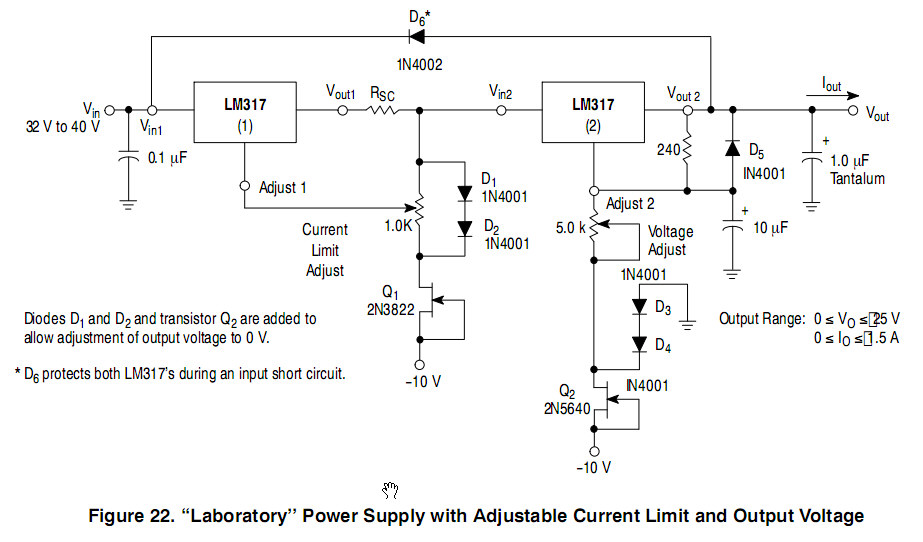
This really isn't a good solution. You have two regulators, each with their own voltage drop and power loss, full load current running through a potentiometer and inability to reduce output voltage to zero. It would be much better to get a proper design using one output stage with voltage and current limiting.

enter image description here

Figure 1. A two LM317 solution for those who insist. Source: ON-Semi datasheet.

See Smartest way to use current limit using LM317? for a full description of a working solution to some of these problems if you wish to continue with LM317s for this application. I give a detailed explanation of the circuit operation in that answer.

\$\endgroup\$
4
  • \$\begingroup\$ You argue for one output stage that hansles both voltage and current regulation, yet you show a design with two separate stages? (And what is "current drop"?) \$\endgroup\$ Commented Apr 30, 2016 at 9:52
  • \$\begingroup\$ I think I covered myself with "if you wish to continue with LM317s for this application". The current drop was a brain seizure. I'll fix it, thanks. \$\endgroup\$
    – Transistor
    Commented Apr 30, 2016 at 10:03
  • \$\begingroup\$ Thanks for your reply. Few questions on the circuit you gave - 1. Is the Current Regulator a Constant Current Regulator, or a Max Current Limit Regulator? I mean, will it allow me to adjust the Current flow at output, or just allow me to adjust max allowed Current Flow at output? 2. Which transistors could I use in place of Q1 and Q2 3. What is the value of Rsc? \$\endgroup\$
    – sribasu
    Commented Apr 30, 2016 at 13:35
  • \$\begingroup\$ (1) When the power supply has adjustable current and voltage limits the load will determine which limits first. If the resistance is low the current will be limited. If the resistance is high the voltage will be limited. Current limit is adjustable. (2) Q1 and 2 are constant current sinks. You need FETs. (3) For Rsc see the linked answer. \$\endgroup\$
    – Transistor
    Commented Apr 30, 2016 at 19:02
1
\$\begingroup\$

is this circuit Practical?

It's nearly practical - the main problem is that you haven't got a decoupler capacitor on the input power to the 2nd regulator in the chain. This will probably cause instability under certain load conditions.

Put another 1uF capacitor at the input pin to ground/0V.

Regarding the power ratings - the 100 ohm resistor is only going to "see" 1.25V between Vout and ref therefore the power is only about 16 mW.

The potentiometer (VR2) is subject to the same current as the 100 ohm i.e. 12.5 mA. Maximum power is when the potk is fully extended to 1k i.e. 160 mW.

VR1 is going to be a problem as per Wouter's answer.

\$\endgroup\$
1
\$\begingroup\$

There is a problem with VR1. At maximum current, the circuit can deliver 1A. The wiper of a normal potentiometer is not rated for such a current.

Calculation: regulate down to 0.5A. That will use 1.2 Ohm of VR1's resistance, in which 0.3 Watt will be dissipated. The full VR1 can easiliy handle this, but the very small part of VR1 you are using in this (0.5 A current-limited) setting lilkely won't. (1.2 Ohm is 0.1% of 1k)

Also note that the scale of VR1 will be far from linear: the above calculation shows that the 1A is fully right, 0.5A is 0.1% back from full.

The 100uF capacitor feels a bit low for my liking. IIR the rul;e of thumb more like 1000uF per 1A.

When ser for 1A and shorted, your output will be 0V, and the first LM317 will take the full 1A current. The input voltage can be sqrt(2)*12 ~ 17V, so the chip will dissipate 17W. That requires some good cooling. (It can be a bit better because the diodes have some drop, but it can get worse due to tolerances in the trafo and the mains voltage).

\$\endgroup\$
4
  • \$\begingroup\$ Thanks Wouter for your reply. I understand the heating problem. And 100uF is my mistake. It should be 1000uF or 2200uF. But I really didn't get the problem with VR1. Please can you explain, what solution you are suggesting for VR1 issue? \$\endgroup\$
    – sribasu
    Commented Apr 30, 2016 at 13:38
  • \$\begingroup\$ Firsts a potentiometer will have a current rating for the wiper. You are likely to exceed it. Second a potentiometer has a power rating for the total track. If you use only a part, it will take only that part of the power rating. You are likely to exceed that. A solution could be an old-fashioned bulky and costly wire-wound potentiometer. \$\endgroup\$ Commented May 8, 2016 at 7:41
  • \$\begingroup\$ Hey @Wouter van Ooijen I managed to create the circuit and using a wirewound type pot. It is working. I just placed the voltage regulator before the current regulator circuit. The only issue is - I used a 18-0-18 Transformer 500mA rated (I intentionally used less current one), R3 changed to 2 Ohm and R1 to 220 Ohm and managed to get only 0-100 mA of Current Regulation. Any idea what went wrong? Is value of higher value of R1 impacting somehow? Ideally 1.25/2 = 0.625mA should be max expected; since my Transformer is 500mA I expected to get approx 450mA of Current, but I didn't. \$\endgroup\$
    – sribasu
    Commented May 30, 2016 at 22:22
  • \$\begingroup\$ I can't see all consequences of what you describe, but why voltage regulation before the current regulation? That defeats the purpose of the voltage regulation. \$\endgroup\$ Commented May 31, 2016 at 5:43

Your Answer

By clicking “Post Your Answer”, you agree to our terms of service and acknowledge you have read our privacy policy.

Not the answer you're looking for? Browse other questions tagged or ask your own question.