1
\$\begingroup\$

Please excuse me if this question is a very obvious one, I have searched on here but my electronics knowledge is very very basic.

Here's what I'm trying to do, I have taken an old Android phone apart, which has 2 surface mount buttons (Volume Up/Volume Down). I am trying to integrate this phone into a different case so it can act as a head unit for a car, and what I'd like to do is wire an incremental rotary encoder to these 2 buttons, so when I turn it clockwise, the volume up button gets 'pressed' and viceversa.

I'm a bit lost when it comes to rotary encoders, I have read up on gray code and all that but I'll admit I'm still very lost.

\$\endgroup\$
5
  • 3
    \$\begingroup\$ This is not something that can be accomplished at the "dummies" level. \$\endgroup\$ Commented May 2, 2016 at 10:02
  • \$\begingroup\$ @IgnacioVazquez-Abrams: Sure it is, see my answer. :) Oh, wait... For some strange reason this question seems to have been closed. :( \$\endgroup\$
    – EM Fields
    Commented May 2, 2016 at 16:05
  • \$\begingroup\$ Carlos: This question has been closed so I can't post an answer, but here are two links that'll get you some pictures, at least. The first: is for a real-world solution you can build for less than a dollar in parts, and the second is for a schematic and plot of an LTspice sim of the circuit. If you're interested I can post a link to the circuit list so you can play with the circuit. \$\endgroup\$
    – EM Fields
    Commented May 2, 2016 at 16:30
  • \$\begingroup\$ Hey @EMFields, thank you so much for the reply! Sorry for not replying earlier, I've been away on business. I'd really appreciate that link you mention :) Thank you so much again, it is greatly appreciated :) \$\endgroup\$
    – Carlos B.
    Commented May 7, 2016 at 6:46
  • \$\begingroup\$ Carlos: I see your question has been taken off of hold, so I posted an answer with everything you'll need. \$\endgroup\$
    – EM Fields
    Commented May 7, 2016 at 13:29

3 Answers 3

1
\$\begingroup\$

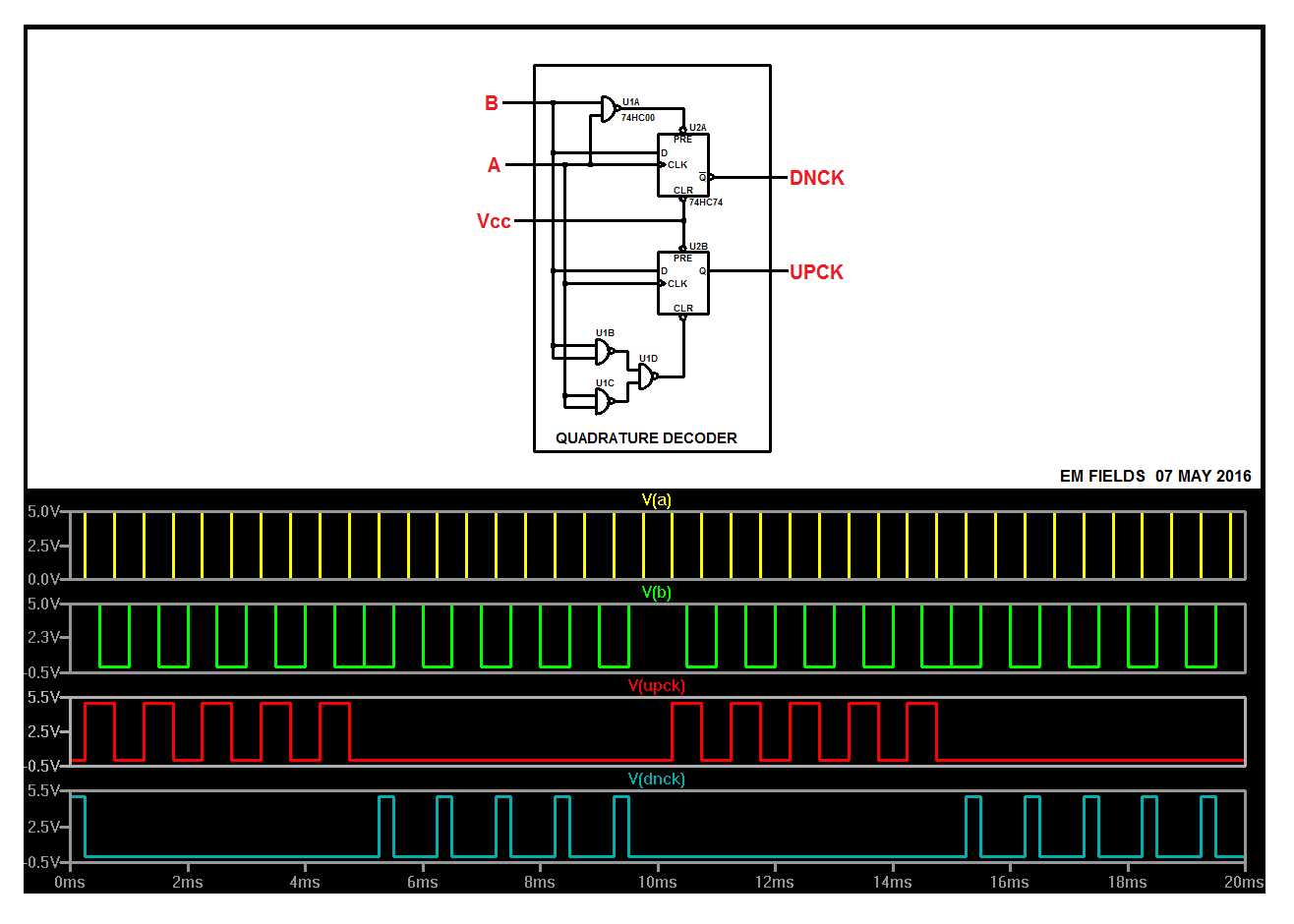
This simulates nicely in LTspice:

enter image description here

and you'll need the following links to get to the files you'll need to run the sim. Download all of the files into the same folder and then start LTspice by left-clicking on the .asc file.

https://www.dropbox.com/s/bubgfvl8ewj5v9g/Quadrature%20decoder.asc?dl=0 https://www.dropbox.com/s/lonoh1d3bucnf1j/74hc04.asy?dl=0 https://www.dropbox.com/s/i9tsv0cjzoof21j/74HC.lib?dl=0 https://www.dropbox.com/s/9h28abp72zhlynj/74hc00.asy?dl=0 https://www.dropbox.com/s/42dmlx4enjzu1op/74hc74.asy?dl=0

\$\endgroup\$
1
  • \$\begingroup\$ That's amazing @EMFIelds! Thank you very much, I'd managed to get the 74HC lib working beforehand :) Thank you once again! \$\endgroup\$
    – Carlos B.
    Commented May 7, 2016 at 14:32
2
\$\begingroup\$

schematic

simulate this circuit – Schematic created using CircuitLab

Figure 1. 2-bit rotary encoder waveforms.

A rotary encoder works by outputting a pair of quadrature (90° offset) pulse trains. These are used to run an up-down counter to keep track of the position. A suitable control algorithm would be as follows:

  • Track the current state of 'A'. If the state changes to 'high' then:
  • Look at input 'B'. If 'B' is low then count up. If 'B' is high then count down.

To get an encoder to do what you want you will need to add some logic to see if it's counting up (clockwise) or down (anti-clockwise) and pass the pulses to the appropriate button input. You won't need to keep track of the actual count.

schematic

simulate this circuit

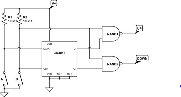
Figure 2. Extracting up and down pulses.

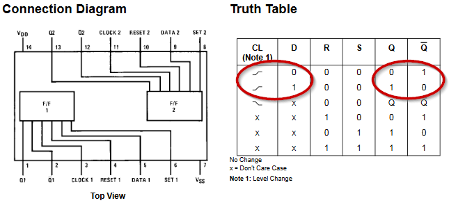
This schematic is to get you started on a solution. A CD4013 D-type flip-flop will update its outputs on each positive-going clock transition based on the 'D' input. Depending on the direction of the encoder rotation either Q or /Q (not Q) will be high. ANDing (or NANDing) these signals with either A or B will give either an UP or DOWN pulse train.

enter image description here

Figure 3. Extract from CD4013 datasheet.

Your next problems will be:

  • How to interface these with the phone. Have a look at CD4016 switches.
  • What happens if the encoder stops with the UP or DOWN stuck on? This may not be a problem if the encoder detents line up consistently with an on or off position of one of the A or B contacts.

Over to you. I'm done.

\$\endgroup\$
3
  • \$\begingroup\$ Thanks for the quick reply! Yes, that seems to tie up with what I've read. Is there any component to do this off the shelf? Or would I need some form of microcontroller? If so, which is the most economical one? Once again, I apologise if these are silly questions, I'm just completely lost on this one. \$\endgroup\$
    – Carlos B.
    Commented May 2, 2016 at 10:23
  • \$\begingroup\$ I'm pretty new to this but looking at the circuit above it seemed to me that it will ALWAYS be high on the output of either NAND1 or NAND2. Sure you'll get the pulses on the other gate but changing direction will just swap the gate that's stuck on high. Even on power up one of those gates will be high. Maybe it's just me not getting it... \$\endgroup\$
    – paulski
    Commented Feb 16, 2020 at 9:20
  • \$\begingroup\$ Welcome to EE.SE. "... looking at the circuit above ..." doesn't work on StackExchange as posts float up and down with votes and user sorting preferences. Instead reference the post or the user. You can also 'ping' the user by using the format @Transistor. Since mine is the only answer using NANDs, I did mention some of the problems in the answer and that the answer is only part of the solution. \$\endgroup\$
    – Transistor
    Commented Feb 16, 2020 at 9:31
0
\$\begingroup\$

What you're describing might be simple if the volume up/down buttons directly operated counter circuitry, but it's unlikely that they do so. More likely, the buttons are sensed by software within the phone that attempts to make the user interface work in a manner which would be helpful for a human operating the buttons (e.g. the longer a button is held, the faster it repeats) but would make it harder to control electronically.

I'd suggest that the most reliable approach is to probably use a microcontroller to send various lengths of up/down pulses to the phone at various rates until you figure out the fastest rate at which pulses can be sent while getting predictable behavior. Then have the microcontroller keep count of how many times the rotary encoder has moved left or right, as well as how many up and down pulses it has sent, and send out pulses whenever the numbers don't match up.

This will be harder than using a simple circuit, but it will mean that turning the knob four clicks to the right quickly will have the same net effect as turning it four clocks slowly. Other approaches are likely to, at best, yield behavior equivalent to holding the up button while you're turning the knob clockwise (but ignoring the speed) or holding the down button while you're turning it clockwise (again ignoring the speed). Not nearly as helpful.

\$\endgroup\$

Not the answer you're looking for? Browse other questions tagged or ask your own question.