0
\$\begingroup\$

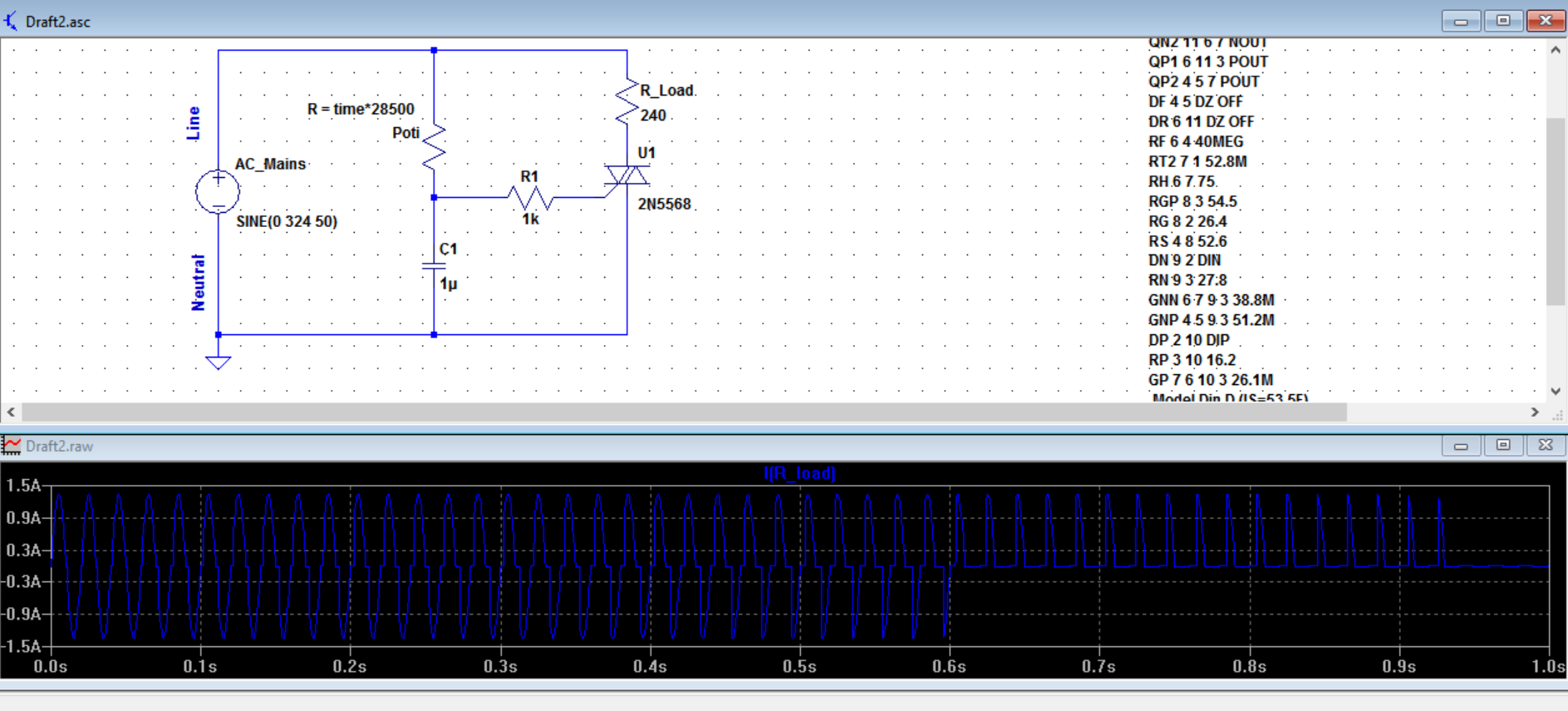
Below is a simple dimmer circuit using a triac, a cap and resistors. As you can see, the resistor Poti changes with time and the load current change can be seen in the plot. It seems like one can use this circuit to control a light bulb light or a single phase AC motor according to the simulation.

enter image description here

But in many literature or tutorials, always a diac is connected to the gate of the triac (and sometimes a fuse added to the Line). Here is an example:

http://www.eleccircuit.com/wp-content/uploads/2010/09/ac-lights-dimmer-with-triac.jpg

My circuit and the circuit in the link have differences. I have the following questions:

1-) Why is a diac used instead of a resistor?

2-) In my circuit I used R1 as 1k value. What is the best value for R1? How can I calculate it?

3-) The circuit in the link has a series 10k resistor next to the potentiometer. Why would that be needed?

4-) Here is another variant: http://www.electronicecircuits.com/electronic-circuits/filament-light-dimmer-circuit What is the job of C2 and R2 here? Suppressing what?

\$\endgroup\$
3
  • \$\begingroup\$ This circuit is not so good, no diac and only one single time constant (R1 C1) network. And here you will learn why it is better to use two times constant circuit. littelfuse.com/~/media/electronics/application_notes/… \$\endgroup\$
    – G36
    Commented May 6, 2016 at 18:45
  • \$\begingroup\$ Yep. Was wondering where the DIAC was. \$\endgroup\$
    – Bradman175
    Commented May 6, 2016 at 23:56
  • \$\begingroup\$ It works in simulation without Diac; why? \$\endgroup\$
    – user16307
    Commented May 7, 2016 at 12:54

2 Answers 2

1
\$\begingroup\$

Your many questions:

  1. The diac allows low power dissipation in the trigger circuit and makes it insensitive to trigger current asymmetry and variations.

  2. Use the diac circuit, or a triac with a built-in diac.

  3. To limit the current through the pot wiper so it is not destroyed when the pot is turned to near minimum.

  4. R2 and C2 are a snubber circuit which limits dv/dt across the triac, preventing false triggering due to stray inductance and perhaps reducing EMI a bit.

\$\endgroup\$
3
  • \$\begingroup\$ Thanks but could you elobrate a bit more on question 1 only? I dont understand it. \$\endgroup\$
    – user16307
    Commented May 6, 2016 at 16:33
  • \$\begingroup\$ The diac triggers at a fixed voltage rather than some very variable and relatively high current, so the trigger angle (from the RC of pot and capacitor ) is both predictable and similar on both the positive and negative half-cycles. The stored charge in the capacitor discharges quickly into the gate providing a large trigger current whilst only requiring a small current through the pot (over a much longer time). \$\endgroup\$ Commented May 6, 2016 at 16:50
  • \$\begingroup\$ "... so the trigger angle (from the RC of pot and capacitor ) is both predictable and similar on both the positive and negative half-cycles." That's the way I learned it. The triac may turn on a slightly different voltages on each half-cycle and the turn-on point may also be temperature dependent. The diac is typically about 20 V and has symmetrical breakdown characteristics. No current is passed until breakdown (eliminating heat of the resistor). Any difference in triac turn-on point is largely basked by the much higher diac voltage. \$\endgroup\$
    – Transistor
    Commented May 6, 2016 at 18:30
1
\$\begingroup\$

The diac "opens" at certain defined level (quite precise) and the capacitor is discharged trough the diac forming a trigger pulse for triac. Once the triac start conducting the capacitor amd series resistor are bypassed, so no more capcitor charging. Without the diac, the trigger signal (not pulse anymore) would be more random angle, in simulation is good but in practice is useless.

\$\endgroup\$

Your Answer

By clicking “Post Your Answer”, you agree to our terms of service and acknowledge you have read our privacy policy.

Not the answer you're looking for? Browse other questions tagged or ask your own question.